ACU ! STEAM ® S-15 ELECTRONIC HUMIDISTAT AND OUTDOOR SENSOR INSTALLATION INSTRUCTIONS April 2014- V1.
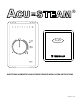
ACU-STEAM HUMIDISTAT, version A Features State of Art digital RH sensor ROOM or DUCT mounting Reprogrammable Microcontroller Potentiometer Set-point setting Out-door temperature sensor for Set-point Reset Green (ON/OFF) and Red (warning) status LEDs Specifications Set-point range. . . . . . . . . . . . . . . 20% to 50% Relative Humidity Accuracy. . . . . . . . . . . . . . . . . . . . ±4.5%, without calibration Linearity . . . . . . . . . . . . . . . . . . . .
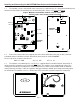
Installing and Connecting the ACU-STEAM Humidistat and the Outdoor Sensor 1.1 The humidity sensor is not located at the same place in a wall mount or in a duct mount humidistat and therefore the two models of humidistats are not interchangeable. Please see Fig.1a and Fig.1b. Jumper - MUST be removed when outdoor sensor is connected - remains in place if the outdoor sensor is not used Jumper Terminal Block GND 24VST1 COM ODR Red LED Humidity sensor Green LED Humidity sensor Fig.
1.4 A two wire control cable is required to connect the outdoor sensor to the terminals marked COM & ODR on the electronic humidistat. Please see Fig. 1d. The outdoor sensor is not polarized so there is no wiring polarity to follow.
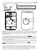
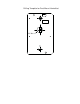
Drilling Template for Duct Mount Humidistat 5/8” dia.