Operation and Maintenance Manual for Electric Boilers (user manual) version: February, 2008 THERM THERM THERM THERM THERM THERM EL 8 EL 15 EL 23 EL 30 EL 38 EL 45
1. CONTENTS 1. CONTENTS ................................................................................................................................................ 2 2. GENERAL USE ......................................................................................................................................... 3 3. GENERAL CHARACTERISTICS OF THERM – EL ELECTRIC BOILERS .................................. 3 4. TECHNICAL DATA ................................................................
2. General use The construction of THERM-EL electric boilers is designed for hot-water heating systems with induced water circulation. They can be installed in central or individual-storey heating with induced circulation sealed or open systems and they are characterized by an environmentally friendly operation without requirements for venting of the combustion product.
thermostat (disjunction of the controlling circuit relay and heating bars) and thus the boiler shut-down occur when the temperature reaches 105°C. Shall the emergency thermostat become disconnected, the boiler can be only put back into operation by an authorized service engineer. Another protection of the boiler is assured by a pressure switch which disengages the control circuit when the heating system water pressure decreases (when there is not enough water in the heating system).
♦ Brief characteristics of the main merits of THERM-EL electric boilers: Simple and intuitive operation The control is designed in a simple, understandable and unambiguous way. Simple operation is also enabled by way of a three-digit LED 7-seg display complemented by an unambiguous signalling system of a series of LEDs. Pump protection against clogging Regular spinning of the pump (once every 24 hours) prevents potential clogging of the pump during an extended boiler down time.
control enables the boiler to operate in a low tariff rate and thus significantly reduce energy costs. Maximum boiler output can be limited in the service menu if the operation must proceed also outside the so-called “low tariff”. !!! Shall other ways of installing the MRC receiver be applied the output of which is one of the phases (MRC/L1 -L3), it is necessary to assure transmission to the R level (reset conductor) by means of e.g. installing an auxiliary relay in the external distributor.
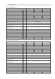
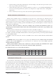
4. Technical data Lower performance series: Nominal heat output Rated current El. components degree of shielding Power voltage / frequency Max. rated current Wiring main circuit breaker Rated current of the control system fuse Electric durability of the relay Mechanical durability of the relay Heating water inlet/outlet Min. service overpressure of the heating assembly Max. service overpressure of the heating assembly Max.
♦ Manufacturing control All boiler parts are checked and correctly set by the manufacturer prior to final assembly. Each boiler is tested on water circuit tightness and the function of the regulating and safety components is set and tested as well. The boiler was manufactured in line with: Standards: CSN EN 60 335-1, CSN EN 60 335-2-30, CSN 06 1008, CSN 07 7401, CSN 06 0810, CSN 07 0240, CSN 06 0310, CSN EN 60 730, CSN 06 0830, CSN EN 60 730-1, CSN 06 1010; Government Regulations: No. 163/2002 Coll.
boiler is installed in the permitted zones, relevant electric current accident protection must be concurrently performed in accordance with the same standard, too. The installation location must be chosen which will allow sufficient access for the operator as well as service inspector. Degree of shielding of the boiler electric components is IP 40.
mount a heating system charge and discharge cock and a sludge cock at the lowest point of the system in the very proximity of the electric boiler separate all electric boiler types on inlet and outlet by stop valves, too (see standards CSN 06 8030), not to be forced to discharge the whole system in case of inspection or repair of the boiler or during filter replacement remove control levers from stop valves and secure them against manipulation.
Non-observance of the aforementioned requirements results in cancellation of the undertaking for the damaged components! ♦ Choice of the regulating and controlling components The boiler is fitted with basic regulatory and safety elements as the following electric diagrams show. Therm-EL boilers can regulate their outputs. They are equipped with their own PID regulation which does not allow heating over the set temperature.
Heating water temperature [°C] Outdoor temperature [°C] Regulation according to room of reference Used in family houses. Only temperature of a selected room is monitored on the basis of which the entire flat environment is regulated. Other rooms with diverse heat losses will be heated to different temperature unless further thermoregulating knobs are not installed on the radiators. This method has the advantage of a more flexible regulation.
6. Boiler operation Description of the control panel: Control panel is simple and intuitive and displays the boiler functions. The panel uses colour-coding and graphical division of the heating and DHW preparation sections. LEDs positioned between the buttons for setting the temperature higher/lower (up/down arrows) are turned on if the 2 particular mode is selected (i.e. either the DHW preparation mode or the heating water mode marked TOP).
7 7x LED indication for the selected functions 6 1 Heating temperature setting buttons °C °C HDO IN OUT bar O/I 3 2 DHW temperature setting buttons O/I SELECT (MENU) (MENU) Heating on/off buttons °C LED display (ENTER) (ENTER) 4 DHW heating on/off 5 Button for the display mode and mode and parameters settings ♦ Error indication ERROR MESSAGES: Error code E.00 E.01 E.02 E.03 E.04 E.05 E.06 E.07 E.08 E.09 E.10 E.
♦ Menu parameters It can be always selected (in the user menu by the diS / P3.2 parameter) whether the item is displayed in the numerical format (more suitable in foreign language versions of the automatic control system) or in the mnemotechnical format (closer to the Czech language). MENU PARAMETERS: Mnemo Numerical format format USER MENU Initial settings Et1 P1.1 CURVE SLOPE AT BININ N.UTL = 0 (night moderation – disconnected) 1.6 Et2 P1.2 CURVE SHIFT 1 Et3 P1.3 CURVE SLOPE 2 AT BININ N.
Adr P6.2 h.01-h.21 MULTIPLE BOILER FORMAT (CASCADE) CONTROL PARAMETER ERROR HISTORY DISPLAY i.01-i.12 SERVICE AND DIAGNOSTIC INFORMATION PARAMETERS SET FOR THE MASTER CASCADE BOILER PCC P7.1 NUMBER OF BOILERS IN THE CASCADE dCC P7.2 SYSTEM CASCADE PUMP DECELERATION dC1 P7.3 BOILER PUMP DECELERATION, IN THE CASCADE, AFTER ITS HEATING OPERATION IS FINISHED AFC P7.4 CASCADE SYSTEM ANTI-FREEZE PROTECTION FREEZE PhC P7.5 MAXIMUM CASCADE OUTPUT WITHOUT MRC SIGNAL P0C P7.
♦ DHW temperature display If any other variable is displayed at the moment (heating water temperature, output, error message etc.), pressing any of the buttons 2 opens the DHW temperature dialogue. This display is indicated by the °C pilot light above button 4. In the case of sensor defect or absence, the numerical data become replaced with dashes: _ _ _ during disconnection or interruption of the sensor or wiring, ¯ ¯ ¯ after a short circuit on the sensor or wiring.
♦ Signal indication of the mass remote control (MRC) The presence of the MRC signal is indicated by the HDO (MRC) pilot light. If it is turned on, it means that the full boiler input is allowed. Reduction of the boiler input by way of MRC signal can be set in the service menu by means of the Ph¯ (P4.4) item. ♦ Displaying the error messages If you press (or double press) the (SELECT) button (5), the error message dialogue opens.
♦ Displaying the instantaneous boiler output If you press (or double press) the (SELECT) button (5), the display dialogue of the instantaneous boiler output opens. This dialogue is indicated by the letter P in the first position of the display. The output is shown in kW (P.2.5 =2.5 kW, P.18 = 18 kW etc.). 8. User menu ♦ Accessing the user menu To access the user menu, press the O/I (MENU) button (3) for more than 2 seconds. To move between the menu items, press the ▲ , ▼ buttons (1).
Group 2: Integrated room thermostat parameters An integrated room thermostat can control heating operation according to the data from internal temperature sensor. It uses proportional control to set the outlet water temperature within the range defined by the tdr (P2.3) parameter: - if TM < ti1 - tdr (TM < P2.1 – P2.3), heating is controlled to reach the maximum heating water temperature to¯ (P3.4), - if TM > ti1 (TM > P2.1), heating is controlled to have the minimum heating water temperature to_ (P3.
connected. In the case of a defective sensor or if it is not connected, the boiler is controlled in the tEr (like at P3.1 = 1) mode. otP 4 Heating is controlled by external regulator which is connected by way of the OpenTherm Plus interface. In the case of defective communication or regulator, the boiler is controlled in the tEr (like at P3.1 = 1) mode. ot- 5 Heating is controlled by external regulator which is connected by way of the OpenTherm Lite interface.
Electric boiler operation is very simple and fast and does not require any special qualification. The boiler can be nevertheless controlled only by adults who have been demonstrably explained the boiler function and operation. This demonstration must be performed by the worker who carried out the installation and set the boiler into operation. If the display is turned on, the control supply voltage is fed to the boiler.
♦ Boiler shut-down You can switch off the boiler for a shorter period by pressing the 0/1button or potentially by the room thermostat switch. If you want to shut the boiler down for an extended period of time outside the heating season (i.e. during summer holiday), it is suitable to switch off the boiler by the external main circuit-breaker (switch) unless there is a potential risk of system freezing or pump clogging (these functions are naturally not available during the complete boiler shut-down). 10.
11.
BT NU TL TB 25 TV OT BL VENTIL N TUV TO L1 L2 L3 N Pe Contactor K2 1,25A 2 DHW Heating REKREL HDO REKCPU MRC OR C 1 2 Blocking element K5 OT communication K3 GND K6 Outdoor temperature sensor PT Re3 B- A+ REKZOB Re2 DHW sensor 1 Night moderation Heating water sensor Re1 Relief relay 1 Relief relay 2 Storage tank thermostat Room thermostat Pressure sensor ♦ Therm EL 15 connection to the power supply 2 1 Safety thermostat Re6 Circulation pump K7 K1 Cascade REKAS1 h K4 Th
NU TL TB 26 TV Contactor K2 OT BL VENTIL N TUV TO L1 L2 L3 N Pe K5 1,25A REKREL HDO REKCPU DHW Heating BT 3 MRC K3 Re8 Blocking element K6 Re7 OT communication OR C 1 2 Re6 Outdoor temperature sensor PT Re3 GND REKZOB Re2 B- A+ 2 DHW sensor 1 Night moderation Heating water sensor Re1 Relief relay 1 Relief relay 2 Storage tank thermostat Room thermostat Pressure sensor ♦ Therm EL 23 boiler connection to the power supply 3 2 1 Safety thermostat Re9 Circulation pump K7 K1
♦ Therm EL 30 boiler connection to the power supply 1 2 Re1 Re2 3 Re3 Re6 Re7 Re8 Re9 4 4 3 2 1 Safety thermostat Re1 Re2 Re3 REKREL Circulation pump REKCPU K6 REKZOB K7 K5 1,25A K1 Contactor Heating water sensor K2 B- 27 VENTIL N TUV TO L1 L2 L3 N Pe BL DHW Heating OT HDO TV MRC TB Blocking element TL OT communication NU Outdoor temperature sensor BT DHW sensor OR C 1 2 Relief relay 1 Relief relay 2 Storage tank thermostat Room thermostat PT h K4 Night mod
♦ Therm EL 38 boiler connection to the power supply 1 2 Re1 Re2 3 Re3 4 Re6 Re7 Re8 Re9 5 4 5 3 2 1 Safety thermostat Re1 Re2 Re3 Re6 REKREL Circulation pump REKCPU K6 REKZOB K7 K5 1,25A K1 Contactor Heating water sensor K2 B- 28 VENTIL N TUV TO L1 L2 L3 N Pe BL DHW Heating OT HDO TV MRC TB Blocking element TL OT communication NU Outdoor temperature sensor BT DHW sensor OR C 1 2 Relief relay 1 Relief relay 2 Storage tank thermostat Room thermostat PT h K4
♦ Therm EL 45 boiler connection to the power supply 4 5 Re1 Re2 6 Re3 1 Re6 2 Re7 Re8 Re9 3 3 2 1 4 5 6 Safety thermostat Re1 Re2 Re3 Re6 Re7 Re8 Re9 REKREL Circulation pump REKCPU K6 REKZOB K7 K5 1,25A K1 Contactor Heating water sensor K2 B- 29 VENTIL N TUV TO L1 L2 L3 N Pe BL DHW Heating OT HDO TV MRC TB Blocking element TL OT communication NU Outdoor temperature sensor BT DHW sensor OR C 1 2 Relief relay 1 Relief relay 2 Storage tank thermostat Room th
REKZOB Pressu re He ating water senso r senso r Room the rmo stat Relief Re lay 1 Relief Re lay 2 Stora ge ta nk the rmo stat Night mo dera tion REKA S1 L3 L2 L1 N PE Cont actor REKZOB L2 L1 N PE T hr ee-wa y va lve Cir culation pum p L3 OT comm unicat io n MRC 1 ,25A Safe ty t herm ostat Master boiler Cascad e REKREL REKCPU DHW senso r Out door tem per atur e sen sor Blocking e lemen t DHW Heat ring L1 L2 L3 N Pe Pressu re He ating water senso r senso r Room the rmo stat Relief R
♦ Connection of the current maximum value monitor to the boiler relief relay terminals Mains (from the electrometer) 3 x 400 V HJ 102 2.st OR 1.st Boiler terminals OR L1,L2,L3 1st degree disconnection 1 2 2nd degree disconnection 1 2A 3 N 12.
superior position with regards to heating and the maintenance of the set temperature always proceeds without time limits (with the exception of the MRC signal). Shall the temperature in the storage tank fall below the set value, the boiler system three-way valve position is set preferentially and the boiler water heats up the external indirect heating DHW storage tank. The DHW preparation can be deactivated by setting the boiler in the SLEEP mode.
14.
15.
16. Wall-mounting of the boiler 17.
18. Record of repairs and annual inspections Performed operation Contractual org. Customer signature Date of record Warning regarding the disposal of the packaging and the product after the end of its service life-time All applied materials comply with the requirements specified in Section 10 of the Act No. 185/2001 Coll. and Section 6 of the Act No. 477/2001 Coll. The product packaging is commonly disposed of in scrap paper collection centres.
CERTIFICATE OF QUALITY AND COMPLETENESS OF THE PRODUCT Electric direct heating THERM EL boiler Type designation: THERM EL .................. Product number: .................................................. The appliance complies with the requirements of the European Directives No. 89//336/EHS, 73/23/EHS and other related technical regulations, standards and recommendations. Its operation under the service conditions in line with manufacturer recommendations is safe.