
Instruction Manual


Owner’s Manual 11
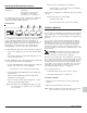
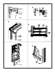
Reinstall the Refrigerator
Your dealer or Norcold authorized service center must do this
procedure.
1. Push the refrigerator completely into the enclosure.
2. Install the screws in the mounting flange at the rear of the
refrigerator.
3. Install the screws from the upper and then the lower mount-
ing flanges on the front of the refrigerator.
4. Put the plastic plugs into the mounting flanges of the
refrigerator.
5. Connect the DC wiring to the refrigerator:
- Connect the DC wires to the refrigerator.
- Install the DC fuse or connect the DC wiring to the battery or
the converter.
6. Connect the black AC power cord and the white ice maker AC
power cord (optional) to the receptacle.
Replacement Parts
You may purchase replacement parts through your local RV
dealer or authorized Norcold Service Center.
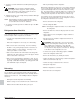
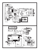
The parts of the ice maker wiring pictorial and diagram are (See
Art01500):
1 ......................................................... 120V AC Hot / smooth
2 ..................................................... 120 VAC Neutral / ribbed
3 ...................................................................... Ground screw
4 ....................................................................... Thermal fuse
5 ........................................................... Solenoid water valve
6 ............................................................................. Ice maker
7 .......................................................................... Mold heater
8 .......................................................................... Thermostat
9 ..................................................................... Shut off switch
10 ........................................................................... Fill switch
11......................................................................... Hold switch
12 .................................................................................. Motor
Ice Maker Wiring Pictorial and Diagram
(Optional)
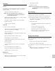
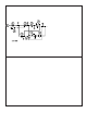
Wiring Diagram and Pictorial
The parts of the wiring diagram are (See Art01769):
The parts of the wiring pictorial are (See Art01770):
A .................................................................... Temperature switch
B .................................................................................. AC heaters
C ..................................................................................Thermister
D ................................................................................ Interior light
E .............................................................................. Divider heater
F .............................................................................. Door contacts
G ............................................................................ Door switches
H ................................................................... Gas valve (optional)
I ............................................................................................. Fans
J ........................................Ice maker water line heater (optional)
K ...................................................... Water valve heater (optional)
L ...................................... Dispenser water line heater (optional)
M ................................... Dispenser water valve heater (optional)
N .........................................................Dispenser valve (optional)
O ............................................................. Fan temperature switch
P ....................................................Temperature switch (optional)
Q ...................................................... Dispenser switch (optional)
R .......................................................... Dispenser light (optional)
S .......................................................................... Igniter (optional)
T .......................................................................... Chassis ground
U .......................................................... Movable door seal heater
V ............................................Movable door seal housing ground
1 ........................................................................ Switched 12 VDC
2 ......................................................... Fused continuous 12 VDC
3 ........................................................................ Communications
4 ............................................................................Display ground
5 .......................................................................... Auxilliary ground
6 ...................................................................... Auxilliary +12 VDC
7 .........................................................................Divider + 12 VDC
8 .................................................................... Gas valve + 12 VDC
F1 .......................................................................... 5 Amp DC fuse
F2 ........................................................................... 8 Amp AC fuse