
Assembly User Manual

Form #19632
Rev. 1/15/08
Tools needed
• Flat-bladescrewdriver •PhillipsScrewdriver
• AdjustableWrench •Scrapingtool
• SocketWrenchwith7/16”socket •Pliers
• SiliconeGrease
• DAPDynaexCaulkorequivalent(availableatmosthardwarestores)
Note:
• Readallinstructionsbeforebeginningwork.
To Remove Toilet From Floor
1. TurnoffRVwatersupplyperRVOwner’sManual.
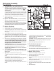
2. Pressbothkeypadbuttonsatthesametime,twice,toopenbladeand
drainbowlofwater.If control or mechanism does not work, you will have
to open the valve manually. Remove the Sound Deadening Insulation
(if present) from the back of the mechanism to access the mechanism
lead screw (Fig. E). Turn knob (if present – otherwise use a 5/16” socket
wrench) clockwise to open the valve.
3. Pry off Bolt Caps with Fla t- bl ad e s cr ew dr iv er . U se
7/16-inchwrenchtoremoveLagScrews.
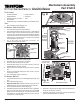
Mechanism Assembly
Part #19613
White Mechanism Plate
Mechanism
Fig. D
Mounting
Flange
Mechanism
Tube Lip
Fig. A
newer plates have
a 2nd hole at front
Switch
box
Fig. B
Mounting Flange
4. TurnoffpowertoToiletatRV’sDCdistributionpanel.
5. TiltToilettowardyoutogainaccesstoconnections.
6. DisconnectToilet’s12-voltpowerhookuptoRV.
7. DisconnectWaterSupplyLinefromelbowconnectorbyhand.Use
AdjustableWrenchifnecessary,withcare.
8. RemoveToiletfromoorandplaceupsidedownontowelorsoftfabric
mat.
9. RemoveoldClosetFlangeSeal(maybefoundontoiletorinoorat
ClosetFlange).Discard.
10. CoverHoldingTankopeningtocontainodor.
To Remove Old Part
1. UsingScrewdriverhandle,tapout2MountingBushings(Fig.B).Save
them.
2. RemoveMountingFlange(Fig.B).
3. High Prole models only:IfExtensionTube(Fig.C)didnotcomeout
withMountingFlange,removeitandtheExtensionTubeSeal.Save.
4. Removeandsave4MechanismScrews(MS,Fig.D).
5. EaseMechanismAssemblyoffwhiteMechanismPlate.TogetMecha-
nismout,youmayneedtoremoveotherparts(Fig.A).ToremoveMetal
Bracket,loosenscrewsandswingout.ToremoveControllerAssembly
and/orSwitchBox,useaat-bladedscrewdrivertoprythemfromwall
ofunit.Removeoldadhesivepad(s).
6. Disconnect2 (green/yellow) Wire Motor Leads from Mechanism As-
sembly(Fig.A).Usepliersifnecessary.
7. DisconnectOverowTubeifpresent(pre3-16-03)fromMechanism
Assembly.DiscardMechanismifnotreturning.
(not present
on all mod-
els)
Fig. C
Shown
separatefor
clarity–these
itemsnor-
mallyremain
assembled
HIGHPRO-
FILEONLY
Extension
Tube
Mounting
Flange Seal
Extension
Tube Seal
Clamp
Mounting Bushing
Controller As-
sembly
Motor Leads
Metal Bracket
Mechanism
RVToiletService Parts
for
Aria/Aria Deluxe