Waste Water Transfer System Système de transfert d’eaux usées Sistema de transferencia de aguas negras
Waste Water Transfer System Système de transfert d’eaux usées Sistema de transferencia de aguas negras Owner’s and Installation Manual Manuel d’installation et d’utilisation Manual de instalación y de uso Installation Installation Veuillez conserver ce manuel pour référence ultérieure. Instalación Por favor conserve este manual para consultas futuras. Veuillez lire TOUTES ces instructions avant d’installer l’unité Thetford Waste Water Transfer System (TWTS).
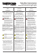
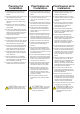
Installation, Con't. ! Installation, suite CAUTION: Do NOT use one- way air admittance valves (also known as cheater vents). Macerating pumps need two-way air movement. ATTENTION : NE PAS utiliser d’évent automatique à clapet (ou évent unidirectionnel). La pompe de macération a besoin que l’air circule dans les deux sens. ! Electrical Cautions: Precauciones eléctricas: Pour garantir un fonctionnement sécuritaire : ■ Do not use in swimming pool or marine areas.
Installation, Con't. Installation, suite Instalación, cont. Required Tools Outils requis Herramientas requeridas ■ Pipe saw ■ Scie à tuyau ■ Cortatubos ■ Phillips screw driver ■ Tournevis cruciforme ■ Destornillador Phillips ■ Flathead screw driver ■ Tournevis plat ■ Destornillador plano ■ 5/16" Socket wrench ■ Clé à cliquets avec douille de 5/16 po ■ Llave para dados de 5/16 pulg.
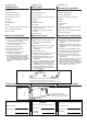
Installation, Con't. Installation, suite Instalación, cont. Parts Included with Thetford Toilet Pièces incluses avec la toilette Thetford Piezas que se incluyen con el inodoro Thetford #14 (2x) (2x) #17 #18 (2x) (2x) (2x) #15 NOTA: Las piezas mostradas a continuación se mencionan en las instrucciones y se aplican al inodoro de descarga posterior y tanque de agua Thetford. Las instrucciones pueden variar si se va a instalar un inodoro de descarga posterior.
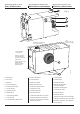
Parts Included with Pump Pièces incluses avec la pompe Piezas incluidas con la bomba Fig. C #1 Pump/pompe/bomba #2 (3x) 90-110mm #6 (1x) (1x) 60-70mm #3 #4 (1x) 2"/(1x) 2 po/ #5 (1x) 2 pulg. ART00119 (3x) 32-50mm (1x) 1-1/2" (1x) 1-1/2 po (1x) 1-1/2 pulg. (1x) (1x) #7 (1x) #11 n tio #9 (1x) #12 M ec rot it P cu Cir (8x) #8 (1x) #10 #13 tch wi lS ua an n tio tec Pro at e erh Ov Part No.
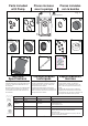
Technical Specifications, Con't. Caractéristiques techniques, suite Especificaciones técnicas, cont. Terms & Dimensions Dimensions et terminologie Términos y dimensiones D F Fig. F G H I J K E 18 5/8"/473 mm (18 5/8 po)/ 473 mm (18 5/8 pulg.) 22 in 9 m 9" d’a clua m ( i n Bla cl dm nt l 9 p dd udi iss e s o) er ng ion ouf Inl fle et t 7 1/4"/ 184 mm (7 1/4 po)/ 184 mm (7 1/4 pulg.) 22 in 9 m de cluid m (9 en a la pu tra c lg da ám .
Planification de l’installation Planning the Installation Planificación de la instalación ■ All plumbing fixtures attached to the pump must be located on the same floor of the building. ■ Tous les articles de plomberie raccordés à la pompe doivent être situés au même étage de l’édifice. ■ Todas las unidades de plomería conectadas a la bomba deben estar ubicadas en el mismo piso de la edificación. ■ The pump will pump up to 18' vertically or up to 150' horizontally with proper slope.
Planning the Installation, Con't. Planification de l'installation, suite Fig. G Planificación de la instalación, cont. 3 Plumbing Considerations Considérations relatives à la plomberie 12 4 Consideraciones de plomería 2 1 5 8 GFCI 9 7 11 6 10 1. The placement of the 120V GFCI outlet location MUST meet local code! Recommend at least 40" away from bathtub or shower and within 6' of the pump. 2. 1-1/4" discharge 3. 1-1/2" vent connected to outside-do NOT use one-way "cheater" vents 4.
Planning the Installation, Con't. Planification de l'installation, suite Planificación de la instalación, cont. Which Installation Best Fits My Site? Quel type d’installation convient à ma situation? ¿Cuál es la mejor instalación para mi sitio? There are three basic installation options. When planning the installation, note overall width of toilet and offset placement of pump; plan for maintenance accessibility! Il y a trois options d’installation de base.
Planning the Installation, Con't. Planification de l'installation, suite Planificación de la instalación, cont. 1.6 GPF Elongated Bowl, Cuvette Allongée, Taza Alargada ! ! Tuyau rigide de 76 mm (3 po) 3A 16" +/-3/4” 406 mm +/- 16 mm #1 ART00182-1 ! ART00182-5A 3" Rigid Pipe Not to exceed 36" 20" +/- 3/4” 508 +/- 20 mm Fixtures on left; Sink on right Accessoires à gauche; lavabo à droite Ne dépassant pas 91,4 cm (36 po) 27.
Planning the Installation, Con't. Planification de l'installation, suite Planificación de la instalación, cont. ■ OPTION D’INSTALLATION #1 : ■ OPTION D’INSTALLATION #2 : ■ OPTION D’INSTALLATION #3 : Pompe et plomberie derrière le mur – il vous faut un tuyau rigide de 76 mm (3 po) et un manchon à tuyau de 76 mm (3 po) (non compris), et les pieds les plus courts (inclus) pour obtenir la pente de drain adéquate.
Install Toilet and Pump NOTE: Unless otherwise noted, steps apply to ALL installation options. Site Preparation Installation de la toilette et de la pompe REMARQUE : Sauf indication contraire, les étapes s’appliquent à TOUTES les options d’installation. Préparation des lieux Instale el inodoro y la bomba NOTA: Los pasos se aplican a TODAS las opciones de instalación a menos que se indique lo contrario. Preparación del sitio Fig.
Install Toilet and Pump, Con't. Installation de la toilette et de la pompe, suite Do not use ! Warning! an extension cord as this is a safety Avertissement! Ne ! pas utiliser de rallonge électrique, car elles présentent des risques pouvant causer des blessures! hazard that can cause injury! ! CAUTION: To permit proper drainage it is essential to elevate the shower/tub drain to a MINIMUM of 9" above the finished floor of the installed pump.
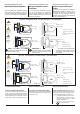
Installation de la toilette et de la pompe, suite Install Toilet and Pump, Con't. Shower/Tub | Douche/Baignoire | Regadera/Tina Instale el inodoro y la bomba, cont. Sink | Lavabo | Lavamanos ! #2 J ! K #4 1-1/2" P3 P2 Vent Line ART00188-2 ART00188-1 2" Conduit d’évent Tubería de ventilación D Slide over plumbing Glisser sur la tuyauterie Deslizar sobre el tubo 20.00” D #2 ART00189-1 ! D D ! CAUTION: To avoid LEAKING, use WRENCH to firmly tighten clamps 25 in - lbs. lbs.
Installations without Toilet Installations sans toilette Instalaciones sin inodoro If C is not attached to a toilet, it MUST be covered with the cap using clamp provided. C #3 Si C n’est pas raccordé à une toilette, il DOIT être recouvert d’un bouchon à l’aide du collier de serrage fourni. ART00088 Si no se conecta C a un inodoro, TIENE QUE cubrirse con la tapa y abrazadera suministrada. #7 Discharge | Évacuation | Descarga ! P1 ! #2 ART00188-3 ! Étape 2.
Install Toilet and Pump, Con't. Installation de la toilette et de la pompe, suite Instale el inodoro y la bomba, cont. Refer to Fig. G for Steps 3-5. Consultez la fig. G pour les étapes 3 à 5. Consulte la fig. G para realizar los pasos 3-5. Step 3. Connect Bath / Shower / Sink Étape 3. Raccordement de la baignoire/douche/lavado Paso 3.
Install Toilet and Pump, Con't. Installation de la toilette et de la pompe, suite Instale el inodoro y la bomba, cont. Step 5. Connect Discharge Line Étape 5. Raccordement du conduit d’évacuation Paso 5. Conecte la tubería de descarga Pump discharge outlet has a built-in check valve. Do NOT install an additional check valve as this may cause the pump to malfunction. ! ATTENTION : La sortie de la pompe comporte un clapet antirefoulement intégré.
Installation de la toilette et de la pompe, suite Instale el inodoro y la bomba, cont. Step 6. Connect Toilet and Pump-Opt 1. Étape 6. Raccordement de la toilette et de la pompe – Option 1. Paso 6. Conecte el inodoro y la bomba. Opción 1. 5 Cannot exceed 36" Ne doit pas dépasser 91,4 cm (36 po) No puede ser mayor de 91.4 cm (36 pulg.) P7 ! 6 ART00187-5A ART00187-4A 4 ART00187-6A Install Toilet and Pump, Con't. P7 3" Tuyau Tubo Rigid rigide de rígido de Pipe 76 mm 76 mm (3 po) (3 pulg.
Install Toilet and Pump, Con't. Installation de la toilette et de la pompe, suite Instale el inodoro y la bomba, cont. Step 7. Assemble & Secure Toilet Étape 7. Assemblage et fixation de la toilette Paso 7. Monte y afiance el inodoro Note: Instructions apply to Thetford Rear Discharge Toilet. Assemble water tank; follow the instruction sheet supplied with Thetford tank BEFORE you begin the steps below.
Install Toilet and Pump, Con't. Installation de la toilette et de la pompe, suite Instale el inodoro y la bomba, cont. Step 8. Prep and Test the System Étape 8. Préparation et essai du système Paso 8. Prepare el sistema y compruebe su funcionamiento 1. Finish connecting all fittings and fixtures. 4. Plug pump into wall outlet. 1. Terminez le branchement de tous les raccords et éléments. 2. Ouvrez le robinet d’arrivée d’eau de la toilette et/ou des accessoires de plomberie. 3.
System Operation, Con't. Fonctionnement du système, suite Funcionamiento del sistema, cont. Thermal Protection Protection thermique Protección térmica Refer to Fig. L item G. If the system overheats, a light comes on indicating that the system is unavailable for use. Once the system cools to an acceptable temperature level, the light will turn off indicating that the system is reset and ready for use. Voir le point G de la fig. L.
Fonctionnement du système, suite 6 Use tool to clear debris. Utilisez un outil pour ôter les débris. Quite la suciedad con la herramienta. 7 1. Open discharge pipe ball-valve. 2. Plug in unit. 3. Flush toilet to test. 1. Ouvrez le robinet à bille du tuyau d’évacuation. 2. Rebranchez l’unité. 3. Actionnez la chasse d’eau pour l’essayer. 1. Abra la válvula de bola del tubo de descarga. 2. Enchufe la unidad. 3. Descargue el inodoro para comprobar su funcionamiento.
Service Kits Fig. M Ensembles de réparation Juegos de servicio SK2 SK6 SK16 SK5 A-B-C SK1 SK12 SK8 SK3 SK13 SK14 SK10 SK11 SK7 SK4 SK9 ART00101B SK15 Description Description Descripción No. N° N.
Thetford Corporation P.O.