Thinkify, LLC TR100 RFID Reader Module Setup Guide and Protocol Reference January 2021 1
Notices Notices Copyright ©2020 Thinkify, LLC. All rights reserved. Thinkify, LLC has intellectual property rights relating to technology embodied in the products described in this document, including without limitation certain patents or patent pending applications in the U.S. or other countries. This document and the products to which it pertains are distributed under licenses restricting their use, copying, distribution and decompilation.
FCC and IC Notice and Cautions: FCC and IC Notice and Cautions: FCC Any changes or modifications to this device not expressly approved by Thinkify, LLC could void the user's authority to operate the equipment. This device complies with Part 15 of the FCC Rules. Operation is subject to the following two conditions: (1) this device may not cause harmful interference, and (2) this device must accept any interference received, including interference that may cause undesired operation.
Modular Use, Procedures, and Integration Instructions The Thinkify module must only be used under the following conditions outlined throughout this document. Voltage: The unit should have a stable and lower noise 5 volt supply from either the USB or the serial interface. Noise should be less than 50 mV peak to peak and the 5 Volts supply should vary less than plus or minus 5% under operation. Heat: The unit should be placed in such a manner that heat is allowed to exit the module.
Modular Use, Procedures, and Integration Instructions Sole Transmitter: This module is to be used alone for the purposes of RFID. This transmitter must not be colocated or operating in conjunction with any other antenna or transmitter. If there are other transmitters co-operational in the immediate vicinity of the TR100 module or if there are are any questions about co-operational transmitters please contact Thinkify.
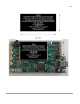
Label: 6
Label: Test Modulation Modes: Test modulation modes, to insure that the TR100 when included within the host device remains compliant, are available from Thinkify upon request. Revision History 7 October 2020 - drafted the TR100 Setup and User's Manual.
About Thinkify, LLC About Thinkify, LLC Thinkify, LLC is a wireless technology company specializing in RFID hardware and software products. With 30 years of combined experience in RFID and over 35 patents in the field, our founding team is one of the technically strongest in the industry. Our focus is embedded RFID. -- Applications where we use RFID to enable common objects, devices and whole environments to become aware of the world around them.
About Thinkify, LLC Table of Contents Notices............................................................................................................................................................................. 2 Note Regarding RF Exposure................................................................................................................................. 2 FCC and IC Notice and Cautions:.....................................................................................................
About Thinkify, LLC “NM" – Macro Control ......................................................................................................................................... 37 "P" – PROTOCOL control (Gen2 Air protocol)................................................................................................. 38 "R" – RF Control......................................................................................................................................................
A Quick RFID Introduction A Quick RFID Introduction Class 1 Generation 2 (Gen2) The RFID tags included in your reader kit conform to the UHF Class 1, Generation 2 (“Gen2”) standard maintained by EPCglobal (http://www.epcglobalinc.org/). EPCglobal is a division of UPC - the same standards organization that controls the barcode numbering system used on retail packaging. This standard (with minor changes) is also maintained by ISO under ISO18000-6C. Most Gen2 tags are passive RFID devices.
Concepts (Performing an Inventory) Concepts (Performing an Inventory) Being an RFID reader trying to read multiple tags using the Gen2 protocol is sort of like being a new teacher trying to take attendance in a kindergarten class... Sadly, the administration didn't give you an attendance list on the first day of class so you have to work it out for yourself. Kindergarten Teacher RFID Reader You have to get a list of everyone's name. You have to get a list of all of the EPC codes from the tags.
Concepts (Performing an Inventory) (Pointing to the next child.) “Mikey who?” she's moved on to the next child. She puts her hand down and sets her state to “Inventoried”. “Jones!” “Pardon me.” “Mikey who?” “You!” (On to the next child.) If the reader doesn't understand the reply it can issue a NAK and try again. “Jones!” Mikey puts his hand down, too and sets his state to “Inventoried”. And off they go... When the teacher reaches the end of the round because she sees no more raised hands, she is done.
Concepts (Performing an Inventory) adjust Q or just try again and let the tags roll a different random number. From your perspective as a user of the reader, these details don't usually matter (we adjust Q for you automatically) but they can be useful to know sometimes if you are trying to optimize performance. Concepts (Reading / Writing other data) The Gen2 protocol is strongly oriented around the use case of rapidly reading the data in Bank 1 of Memory, the EPC.
Thinkify Reader Protocol Overview Thinkify Reader Protocol Overview Here we give an overview of the Thinkify Reader Protocol message structure and provide a high-level summary of the major command groups available to the user. The Thinkify Reader Protocol (TRP) is a human-readable ASCII protocol that allows users and applications to set parameters for RF control, tag list acquisition, tag programming, and digital I/O behavior.
Command Structure part of a message. – The Carriage Return character (0x0D). Upon receipt of a carriage return, the Reader will attempt to parse the command message and, if it is properly formatted, execute the command. Reader Replies The reply the Reader makes to Host commands are also ASCII strings. Replies may either be a single line or a multi-line reply, depending on the Command. Each line of a reply is terminated with a Carriage Return + Line Feed character pair, CRLF (0x0D,0x0A).
Command Structure Examples 1. Set the General Purpose Output (GPO) Pin 1 to a High Level: The Host would send the string: G11 The Reader would respond with: GPOUT1=1 READY> 2.
Command Structure 4. Tn Command: The Tn (T1, T2, ...T6) commands repeatedly perform inventories until interrupted by the Host. During this time the Reader streams tag data until a character is received from the Host. The reader then stops the Inventory sequence and terminates the reply.
Command Reference Command Reference Summary Main Command Description Command Group A RX Amplifier Control Engineering / Test B Enter Bootloader System C Low-Level Chip Registers Engineering / Test D Diagnostic Functions Engineering / Test F RX Filter Control Engineering / Test G GPIO Control GPIO Control and Triggering I Inventory Control Tag Commands K Kill / Access Data Descriptors Tag Commands L Low-Level Tests Engineering / Test M Tag Masking Tag Commands P Protocol Ai
"A" – RX Amplifier Control "A" – RX Amplifier Control A[[]] The “A” command and sub-commands are used to set and get the parameters that control the characteristics of the amplifier in the base band receiver. Sub-Commands Sub Command A Legal Values for SET Description Report all RX Amplifier settings. - AA 8 dB mixer attenuation control. 0=Off, 1=On. 0..1 AG Gain adjustment: 0..6 Value Gain 0 1 2 3 4 5 6 0dB -9dB -6dB -3dB +3dB +6dB +9dB AH Hysteresis: 7 steps of 3dB each.
"BOOTLOADER" – Enter Bootloader "BOOTLOADER" – Enter Bootloader BOOTLOADER Places the reader in a special mode where it is waiting to receive a firmware upgrade. In this state, the reader will not respond to normal commands and requires a power cycle to return to normal operation. See Appendix A for how to upload firmware using the Thinkify Upgrade Utility. Note: Entering bootloader mode un-enumerates the USB port in Windows. Reset into normal code re-enumerates port.
"C" – Low-Level Chip Control Registers "C" – Low-Level Chip Control Registers C[[]] – See table, below. C – Sets a register. ADDR may be one or two nibbles. VAL may be 2 or 6 nibbles. The “C” command and sub-commands are used to set and get the low-level control registers in the AM3392 chip. (This is an engineering command.) Sub-Commands Sub Command C Description Report all control registers.
"C" – Low-Level Chip Control Registers Sub Command Legal Values for SET Description Register Description 0x13 0x14 CLSYS ANAOUT (word) 0x15 MOD control (word) 0x16 PLL main control (word) 0x17 PLL aux control (word) 0x18 DAC reg (byte) 0x19 0x1A RXLen1 (byte) 0x1B RXLen2 (byte) 0x1C 0x1D TXLEN1 (byte) 0x1E TXLEN2 (byte) CS Report all shadow registers - CR Resets all registers to program default.
"F" – RX Filter Control "F" – RX Filter Control F[[]] The “F” command and sub-commands are used to control the RX baseband filter. These commands may be used in troubleshooting and regulatory testing. (This is an Engineering test function.) Sub-Commands Sub Command Description Legal Values for SET - F Report current filter settings. FL Low Pass Value 0..7 FH Hi Pass value 0..7 FB Bypass Filters Bit 0 = 40 KHz Bit 1 = 160 KHz 0..3 FS AC Speedup. 1=On, 0=Off. 0..
"G" – GPIO Settings "G" – GPIO Settings [[]] The G command and sub-commands are used to control the GPIO port. These may be used to set/retrieve GPIO pin settings or to set the reader up for triggered reading. Using the GT command, the reader may be configured to read tags in any of the supported inventory modes for either a fixed time after an edge transition or while a pin is held in a particular state.
“I” – Inventory Control “I” – Inventory Control I[[]] The I command and sub-commands are used to set and get the parameters that control the flow of the Gen2 anti-collision algorithm. Modifications to the default parameters may be helpful in cases where there are a large number of tags in the field or when it is desirable to increase the number of redundant reads for a given tag.
“I” – Inventory Control Sub Command Legal Values for SET Description inventory cycle. (Allows duty cycling for low power applications.) This is a DECIMAL quantity ranging from 0 to 99999 msec. IQ Gen2 Q Parameter The Q used in the QUERY that starts the round 0..8 IS Gen2 Session The session (0 to 3) that will be used for the entire inventory run. 0..3 IT Inventory Target Defines whether the QUERY that initiate round is looking for tags in the A or B state 0..
"K" – Kill, Lock, Access Descriptors "K" – Kill, Lock, Access Descriptors K[[]] The K family of commands are used to control lock kill and access command behavior. The K commands allow the user to get/set passwords used in kill, lock and access operation and specify lock type for the lock commands. The Kill, Lock and Access commands are described in detail in the EPC Global C1G2 specification: uhf c1g2_standard- version 1.2.0.
"K" – Kill, Lock, Access Descriptors There are five sections of memory that can be each individually locked: 1. Kill password 2. Access password 3. EPC memory 4. TID memory 5. User memory The Gen2 protocol specification referenced above describes the data fields associated with the Lock command. The data is a 20 bit number consisting of a 10 bit Mask field and an associated 10 bit action field. In the Insight reader, we use this number with the KL command lock descriptor to control the Locking behavior.
"K" – Kill, Lock, Access Descriptors KAR KL Resets Access password to the default. - Get or set the Lock Descriptor.
"K" – Kill, Lock, Access Descriptors Perform an inventory and look at the results t61 STARTINVENTORY TAG=3000E2001AC1909F6580000EED95 902250 00 0 E Q 0AD5 XRD0=1111111122222222 XRD1=5F7D3000E2001AC1909F6580000EED95 XRD2=E2003414011F0100 XRD3=00000000 STOPINVENTORY 0x004D EPCCOUNT=1 you can see the access password is 22222222 setup the lock descriptor to lock (not perma) the kill and access passwords. This is the 20 bit number described in the table above. 10 Mask bits and 10 Action bits...
"K" – Kill, Lock, Access Descriptors kl0 ACTIVE=0 LOCKBITS=A0280 Try to read without access: t6 STARTINVENTORY TAG=3000E2001AC1909F6580000EED95 902250 02 0 E Q 4A35 XRD0=TAG ERRORCODE 04 XRD1=5F7D3000E2001AC1909F6580000EED95 XRD2=E2003414011F0100 XRD3=00000000 STOPINVENTORY 0x004A EPCCOUNT=1 You can't see the access password or kill password! Use the right access password and go into secure state: ka22222222 ACCESSPASSWORD=22222222 t61 STARTINVENTORY TAG=3000E2001AC1909F6580000EED95 902250 03 0 E Q 6812 A
“M" – MASK / SELECT control “M" – MASK / SELECT control M[[]] As mentioned in the introductory sections, an inventory may begin with the issuance of one or more Gen2 SELECT commands to determine which tags participate in the inventory round. When the Select loop runs (see the IW command) each pass through the loop can issue up to four (4) independent Select commands. The parameters associated with these Select commands are stored in the reader's list of Masks.
“M" – MASK / SELECT control Sub Command Description Action Matching Non-Matching 0 assert SL or inventoried → A deassert SL or inventoried → B 1 assert SL or inventoried → A do nothing 2 do nothing deassert SL or inventoried → B 3 negate SL or (A → B, B → A) do nothing 4 deassert SL or inventoried → B assert SL or inventoried → A 5 deassert SL or inventoried → B do nothing 6 do nothing assert SL or inventoried → A 7 do nothing negate SL or (A → B, B → A) 0=Access & Kil
“M" – MASK / SELECT control Now recall the structure or the Mask command and its parameters: M + MASKNUM + ACTIVE + TTYPE + ACTION + MEMBANK + LEN(1 byte)+ EBV(1 byte MIN) + DATA To set mask #0 to look for “BAAA” in the right position we'd say: M + 0(mask) + 1(enable) + 0(ttype) + 0(action)+ 1(EPC bank) + 10(16 bits) + 20(pointer) + BBAA(data) Our mask command would be: M010011020BAAA We try this out below...
“M" – MASK / SELECT control 36
“NM" – Macro Control “NM" – Macro Control The Macro is a place to store and save reader settings that are preserved even after a device power off/on or BRS (reset command). Sub Command Description NMA Macro Append - add to the end of the macro list without erasing the rest (so you can add settings without typing the whole thing over) NMC Erase the macro list NMP Play the macro list (will be done automatically on reset). NMW Erase current macro list first, type END to stop the writing operation.
"P" – PROTOCOL control (Gen2 Air protocol) "P" – PROTOCOL control (Gen2 Air protocol) P[] = 0..2 = 0..3 = 0..4 The reader supports a number of different data rates and modulation modes for communicating with Gen2 RFID tags. This functionality is controlled by the P command. Read performance is closely tied to how the various modulation, tag signaling and data rate parameters interact in a particular use case.
"P" – PROTOCOL control (Gen2 Air protocol) “P” Command Examples Read the current settings Set 25 uS TARI, Miller 4, 250 kHz LF READY>p TARI=12.5 M=M8 LF=250 READY>p222 TARI=25.
"R" – RF Control "R" – RF Control R[[]] The R command and sub-commands are used to monitor and control radio functions for power and RF frequency. -These commands are used during regulatory testing or under FCC Part 90, licensed operation of the device they are not to be changed outside of the specified limits except by qualified installers. Sub-Commands Sub Command RA Description Legal Values for SET RF transmitter attenuation control.
"R" – RF Control The RA setting The RA setting controls power output. Higher values yield lower output powers. The command RA for output can be set from 8-19 on the TR-100. Higher RA setting, for example RA19, means lower output power. Lower RA setting, for example RA8, means higher output power. In normal, unlicensed operation, the RA value should not be set below its factory default value. The default/minimum value is reported with the “RA” command after a reader start up.
"RP" and "RM" – Multiplexing (Antenna Control) "RP" and "RM" – Multiplexing (Antenna Control) Sub-Commands Sub Command RP RP Description Legal Values for SET Show Antenna numbers in the inventory output RPE to enable and RPD to disable Select the antenna to read from. Only use that antenna until a new antenna is selected. Using the RP command tells the reader to read from only one antenna.
"RP" and "RM" – Multiplexing (Antenna Control) RM4 or RM4 • This mode is mostly intended for RAIL operation, but could be used for GEN2 if desired (maybe with sub-optimum results) • The amount of time spent on each antenna is set in the command RM5 Sets Mux Mode 5 n/a or • Mode 5 is used to select specific antennas to RM5 seq
"T" – Initiate INVENTORY "T" – Initiate INVENTORY T T[] Attempt to read tags using the current settings. The “T” command The T command performs a full dual-nested loop sequence of: SELECT / QUERY / ACK / REQRN / ACK / XREAD / XWRITE, reporting tags as they are found, performing XDATA operations, and attempting to force found tags into the opposite A/B state.
"T" – Initiate INVENTORY The output of the T command is formatted like this: STARTINVENTORY TAG= TAG= … TAG= STOPINVENTORY 0x EPCCOUNT= Each tag's EPC (including the PC word that precedes it) is listed on its own line, with “Tag=” in front of it.
"T" – Initiate INVENTORY T sub-commands perform the same inventory action as the odd-numbered subcommands that precede them, except more information is provided in the tag report besides just “Tag=”: TAG= In all of the T commands, sending the command alone causes the command to execute repeatedly, until a character is received over the interface port.
"T" – Initiate INVENTORY “T” and “T” Command Examples Basic “Get Tags” READY>t5 STARTINVENTORY TAG=3000E2003411B801010861355058 TAG=3000BAD100000000000000000000 TAG=3000E2003412DC03011827047484 STOPINVENTORY 0x0221 EPCCOUNT=3 Get Tags, Including EPC DATA READY>t6 STARTINVENTORY TAG=3000E2003411B801010861355058 923250 00 02 01 06 3 FB66 TAG=3000BAD100000000000000000000 923250 00 02 02 02 2 FB82 TAG=3000BEEF00000000000000000006 923250 00 02 09 00 1 FBAE STOPINVENTORY 0x00FA EPCCOUNT=3 Perform a Continu
"T" – Initiate INVENTORY TAG=3000BAD100000000000000000000 908250 00 5 0 I D3EB TAG=3000BAD100000000000000000000 908250 03 5 0 I D3FC TAG=3000E2003411B801010861355058 908250 02 A 7 Q D409 STOPINVENTORY 0x0062 EPCCOUNT=6 Calculating Signal Strength (RSSI) from the I/Q Magnitude Fields Tag data returned from a Tn inventory (where n= 2,4,6) include fields for I and Q signal magnitude.
"X" – eXtra Data Read and Write Descriptor Control "X" – eXtra Data Read and Write Descriptor Control X[[]] Anytime an EPC code is acquired from a tag, an opportunity exists to either read additional data from the tag, or write data to it. These options are controlled by XDATA descriptors managed by the X commands. The TR265 reader maintains four (4) XDATA read descriptors and four (4) XDATA write descriptors that may be individually configured to perform read/write operations.
"X" – eXtra Data Read and Write Descriptor Control Sub Command Description XW XWR XW<#> XW<#> XW<#><...> Legal Values for SET 1..8 (# of words to read) Word pointer into memory (1-4 bytes) Report all XDATA write descriptors. - Reset all XDATA write descriptors. - Report a given XDATA read descriptor. 0..3 Set the flag for XDATA write descriptor <#>. 0..
"X" – eXtra Data Read and Write Descriptor Control READY>t51 STARTINVENTORY TAG=3000E2003411B802011029356733 XRD0=E2003411B8020110 STOPINVENTORY 0x0039 EPCCOUNT=1 Read Extra Data in T Command // Do 10 (0xA) iterations of T6 READY>t6A STARTINVENTORY TAG=3000E2003411B802011029356733 XRD0=E2003411B8020110 TAG=3000E2003411B802011029356733 XRD0=E2003411B8020110 TAG=3000E2003411B802011029356733 XRD0=E2003411B8020110 TAG=3000E2003411B802011029356733 XRD0=E2003411B8020110 TAG=3000E2003411B802011029356733 XRD0=E
"X" – eXtra Data Read and Write Descriptor Control // Bank:1, WordPntr:02, Len:03, // Data:AABBCCDDEEFF READY>xw011302AABBCCDDEEFF WRDESCRIPTOR=0 ACTIVE=1 BANK=1 LEN=3 PNTR=02 WRITEDATA=AABBCCDDEEFF // Read the tag again // (automatically performs the write).
"X" – eXtra Data Read and Write Descriptor Control TAG=3000111122223333444429356742 919750 03 C E Q CC07 XRD0=SUCCESS TAG=3000111122223333444429356742 919750 01 C E I CC29 XRD0=SUCCESS TAG=3000111122223333444429356742 919750 00 C E I CC4E XRD0=SUCCESS STOPINVENTORY 0x014F EPCCOUNT=7 53