
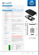
User's Manual


3millID 9249 S. Broadway Building #200 Suite 826 Highlands Ranch CO 80129
+1 303 475 4972
sales@3millid.com
© 3millID
100-02640-A
www.3millid.com
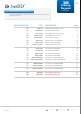
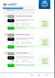
Remove module securement screw. Lever bottom edge of reader module away
from the backplate, and lift up.
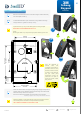
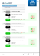
Fix reader BACKPLATE to a plain surface finish, using suitable screw fixings
having a diameter no greater than 4mm (0.15 inch).
If printed full scale, you may use the drawing below as a fixing template.
MEASURE and CHECK DIMENSIONS before use.
NOTE:
Mounting this reader on (or near) metal may impair the read range of the unit.
3. installation guide
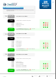
Fasten the reader module, ensuring the top-edge fixings engage correctly with the
recesses at the top of the backplate. Swing the bottom edge of the module down
and forward until you feel the unit ‘snap’ shut.
Secure the module to the backplate using the M3x10mm screw supplied.
If required, you may opt to use a security screw to the sizes shown here.
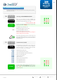
Following installation, it is recommended the access control system and control
units are subjected to a maintenance and operational test procedure.
TEST COMPLETE SYSTEM AT LEAST ONCE A YEAR
i
1
2
i
3
1
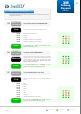
Once the backplate is
secured, make wire
connections to the reader, in
accordance with the screw
terminal connections shown
on Page 3 of this document
and your control panel
requirements. Ensure the
cable does not impair or
prevent the reader module
being secured.
i
2
3
83.3mm (US)
3.3 inches
60.3mm (UK/EU)
2.4 inches
53.0mm
2.1 inches
53.0mm
2.1 inches
15mm
0.6 inch
centreline
BACKPLATE
Fixing holes - 4mm
maximum diameter.
MANUAL
3M
S-Gang
Keypad
4