OWNER’S MANUAL FREEDOM 458 Series COMBI INVERTER/CHARGER TM MODEL 15 MODEL 15D MODEL 20 MODEL 20D Part No. 81-1510-12 Part No. 81-1520-12 Part No. 81-2010-12 Part No. 81-2020-12 INFORMATION IN THIS MANUAL IS SUBJECT TO CHANGE WITHOUT NOTICE ® A Valley Forge Company 1 Part No. 90-0123-00 Libertycombi.
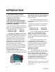
Thank you for purchasing a Heart Interface Freedom 458 Series CombiTM Inverter/ Charger. Heart Interface takes pride in manufacturing quality products specifically designed to meet your power requirements. Freedom Combi Inverter/Chargers provide silent, efficient and reliable AC power for a variety of applications. They feature “hands-free” operation, automatic 3-stage battery charging and automatic AC transfer switching. For your convenience, service is available world-wide by qualified service centers.
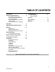
TABLE OF CONTENTS Introduction. . . . . . . . . . . . . . . . . . . . . . . . . 4 Things You Should Know . . . . . . . . . . . . . 5 Circuit Breaker Protection Thermostat Controlled Cooling Inverter Idle Circuit Low and High Battery Shutdown Power Sharing Temperature Sensitive Charging Troubleshooting . . . . . . . . . . . . . . . . . . . . .31 LED Fault Status Things to Check Glossary . . . . . . . . . . . . . . . . . . . . . . . . . . . .33 Specifications . . . . . . . . . . . . . . . . . . . . . . . . .
INTRODUCTION This owner’s manual describes the Freedom 458 Series CombiTM Inverter/ Chargers from Heart Interface. These units perform three distinct functions: power through directly to the loads. When the external AC power source is disconnected, the transfer switch allows automatic switching back to the inverter. 1. DC to AC power inverting. 2. Automatic transfer switching between inverter power and incoming AC power. 3. Automatic 3-Stage Battery charging plus manual battery equalizing.
THINGS YOU SHOULD KNOW Circuit Breaker Protection The Freedom Inverter/Charger is supplemental breaker protected. The INVERT/CHARGE breaker on the front of the unit protects against sustained inverter/charger over current conditions. The 30 Ampere AC INPUT circuit breaker protects the incoming AC circuit. The incoming AC circuit provides power to the battery charger and its power is transfered to the loads connected to the inverter AC output. These breakers are reset by pushing the button back in.
THINGS YOU SHOULD KNOW Temperature Sensitive Charging When the supplied battery temperature sensor is connected to the unit and the batteries, the charge voltage is controlled based on battery temperature. The charger adjusts the charge voltage to the best level, minimizing water loss in wet cell batteries. Charge voltage regulation optimizes the battery life cycle. TSC Sensor Battery Freedom 20D 6 Part No. 90-0123-00 Libertycombi.
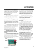
OPERATION The Freedom Inverter/Charger provides 120 volt AC power from auxiliary DC batteries, automatic battery charging and automatic AC transfer switching between an external AC source and inverter mode. External AC Power When external AC power is available, the 3-stage battery charger, transfer switching, and Power Sharing automatically function.
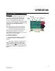
OPERATION STATUS LEDs Each Status LED performs two functions, providing battery type selection and operation status. Status LEDs NOTE: When AC power is available, the default setting for the charger is ON. If the unit was manually turned OFF and AC power is interrupted and becomes available again, the charger will return to ON.
OPERATION LOW BATTERY & OVERTEMP/OVERLOAD - Red LEDs Overtemp • When both LEDs are blinking, an AC backfeed has been detected. A backfeed Low Remote Battery occurs when AC power from an external source is connected to the output of the inverter. Inspect wiring for possible input/output wiring error. This condition will damage the unit and must be corrected before further operation.
OPTIONAL REMOTE CONTROL PANELS Remote Control Panel An optional remote control panel is available. The LED bargraphs on the remote control panel shows battery voltage and DC current in both inverter and charger modes. Easy to see red, yellow and green LEDs show the battery state-of-charge. Power Sharing, charger ON/OFF, inverter ON/OFF controls are provided. Set up features include selection of Idle Threshold, Battery Type and Battery Capacity.
BATTERIES Wet cell batteries will give off gas as a natural result of charging and will experience some water loss. It is very important that the electrolyte level be checked frequently and topped off with distilled water when necessary. Follow the battery manufacturer’s recommendations for maintenance. Never allow the top of the battery plates to be exposed to air, as contamination of the cell will result. Keep the top of batteries clean.
BATTERIES Beware of so-called maintenance-free batteries. These batteries have calcium alloyed with the lead and hold the liquid electrolyte in a sponge-like material. They are sealed and water can not be added. Do not confuse them with true gel cell or AGM batteries, they will not hold up well to deep discharging and repeated cycling.
BATTERIES Parallel Connecting two batteries in parallel will double the Amp-hour rating of the battery bank, while the voltage will be the same as each individual battery. Example, two 12 volt 105 Amp-hour batteries in parallel will produce one 12 volt 210 Amp-hour battery bank.
BATTERIES To achieve 50% cycling you should calculate your Amp-hour consumption between charging cycles and use a battery bank with twice that capacity**. Each AC appliance or tool has a rating plate on it and will be rated in either AC Amps or Watts or AC VA (Volt-Amps) apparent power. To calculate Amphour consumption, use one of the formulas to the right to calculate the DC Amp-hour draw for a 12 volt system. Calculate the Amp-hours for every AC appliance or tool that will be operated on the inverter.
BATTERY CHARGING Battery Charging Completely charging wet cell deep-cycle batteries requires the battery voltage to be raised beyond what is known as the gassing point. This is the voltage at which the battery begins to bubble and gas is given off. If charging stops short of this point, sulfate is left on the plates and deterioration of the battery begins. The gassing point will vary with battery temperature. At 77 degrees F, the gassing point of a 12 volt battery is about 14.0 volts.
BATTERY CHARGING NOTE: Freedom battery chargers are ON whenever AC power is connected to the charger input. The charger can be turned OFF using the CHARGE switch on the front of the unit. This sequence will occur each time external AC power is available. The charger can be turned ON/OFF using the Remote Control Panel or Link Instrumentation. Each time the battery charger is engaged, the 3-stage charger proceeds automatically, resulting in an efficient complete charge and safe battery maintenance.
BATTERY CHARGING Gel cell and Advanced AGM batteries can accept a higher rate of charge. Consult the manufacturer for specifications. Stage 2 - Acceptance Charge The acceptance stage immediately follows the bulk charge stage. During this stage the battery voltage is held constant at the bulk charge voltage limit and the current gradually ramps down. During this stage the battery is accepting its final amount of charge current and the last of the sulfate on the plates is removed.
BATTERY CHARGING The equalizing charge is a timed, 8-hour cycle. The cycle can be ended early by interrupting the AC power to the charger at any time during the cycle. Equalizing should only be engaged after the batteries have been fully charged by a normal battery charging cycle. During this equalizing stage, the battery voltage will increase to the equalize voltage. This will cause the battery bank to gas profusely and will accomplish the following: 1. Removal of residual sulfate.
BATTERY CHARGING WARNINGS 1. Do not equalize gel cell batteries. Check remote default settings. 2. Always monitor the equalize charge cycle. Provide proper ventilation for battery fumes. Do not allow any sparks during equalizing. If one or more cells begin to overflow, terminate the equalize cycle. 3. Check the battery electrolyte both before and after the equalizing charge. Do not expose the battery plates to air. Leave the battery caps on while equalizing. Top off after equalizing. 4.
BATTERY CHARGER VOLTAGE SETTINGS TEMP TYPE 0 TYPE 1 TYPE 2 TYPE 3 Wet Cell Gel 1 * Gel 2 * AGM °F °C AC C EPT FL OAT ACCEPT FL OAT ACCEPT FL OAT AC C EPT FL OAT 120 49 12.5 12.5 13.0 13.0 13.0 13.0 12.9 12.9 110 43 13.6 12.7 13.5 13.0 14.0 13.4 13.9 12.9 100 38 13.8 12.9 13.7 13.2 14.1 13.5 14.0 13.0 90 32 14.0 13.1 13.8 13.3 14.2 13.6 14.1 13.1 80 27 14.2 13.3 14.0 13.5 14.3 13.7 14.2 13.2 70 ** 21 ** 14.4 13.5 14.1 13.6 14.4 13.
INSTALLATION PRECAUTIONS CAUTION This equipment is not ignition protected and employs components that can produce arcs or sparks. To reduce the risk of fire or explosions, do not install in unvented compartments containing batteries or flammable gasses or areas in which ignition-protected equipment is required. WARNING For continued protection against risk of electric shock, use only the ground-fault circuit interrupter (GFCI) type receptacles detailed in this manual.
INSTALLATION CAUTION Risk of electrical shock. Do not remove cover, no user serviceable parts inside. Refer servicing to qualified service personnel. The Freedom Combi is appropriate for installation in recreational vehicles (RV), and other applications. It is recommended that installation be completed by an authorized Heart Interface technical dealer or experienced electrician. Key Installation Points 1. The unit is designed to mount horizontally (on a shelf). 2.
INSTALLATION 9. Do not back-feed the AC output of the inverter with incoming AC power. A back-feed occurs when AC power from shore power or generator is connected to the output of the inverter. This will damage the inverter and void the warranty. Remember that incoming AC must be fed only to the AC input and never the AC output. Always check for AC voltage before connecting wires to the AC output. Do NOT turn the inverter ON until all AC connections have been made.
INSTALLATION Grounding For safety purposes, the chassis of the inverter/charger must be connected to your AC ground system. Use 8 AWG bare copper or green insulated wire, strip one end and use a screwdriver to secure it to the chassis ground bonding lug on the side of the unit. This wire will connect to the ground in your AC electrical system. Make sure the connection is clean and tight.
INSTALLATION AC Wiring The AC wires route through the strain relief mounted in holes on the front of the unit. Use a screwdriver to remove the screws which secure the AC wiring compartment cover plate. Depending upon which model you have, there can be one or two AC inputs and one or two AC outputs within the AC wiring compartment. The labeling for the pigtails is on the front of the unit and is visible when the cover plate is removed. Note: Green wires are connected to the AC Ground Strip. Black . . . . . .
INSTALLATION Ground Fault Circult Interrupters To conform to NEC regulations, certain branch circuits must be equipped with a Ground Fault Circuit Interrupter (GFCI). Please consult the code or a qualified electrician for details. Any such branch circuits must be protected by a brand rated circuit breaker consistent with the GFCI rating. Underwriters Laboratories has tested the following GFCI, and its use is recommended.
INSTALLATION • Remove the positive (+) battery cable terminal cover from the unit and attach the battery cable. Tighten the battery terminal bolts to a torque value between 160 inch-pounds and 180 inch-pounds. Replace the cover for the positive terminal. The negative (-) cable should be connected directly to the negative post of the house or auxiliary battery bank or the ground side of a current shunt. Tighten securely.
INSTALLATION Battery Cable Fusing A fuse is required by the NEC to protect the battery and cables. A UL Listed DC rated slow blow fuse must be installed in the positive (+) battery cable, within 18 inches of the battery. Recommended Fuse: UL Listed Class T JLLN with a DC Rating. This fuse with fuse holder is available from your dealer or Heart Interface.
INSTALLATION Follow these instructions to insure proper start up and confirm that the installation is correct. 1. Check to make sure Invert and Charge are OFF. The INVERT LED should not be illuminated, the CHARGE LED should be blinking (charger ready but no external AC power available). If using a Remote Control Panel or a Link Instrument, make sure inverter and charger are OFF. 2. Check battery polarity. If the unit was connected to the battery with reverse polarity, the unit will be damaged. 3.
INSTALLATION • Testing for backfeed. If a backfeed condition is indicated, disconnect from shore power and disconnect the AC output wires on the inverter. Make sure the inverter is OFF. Apply shore power and measure for voltage between the black and white wires that were attached to the inverter output feeding the electrical panel or loads, not the inverter output wires. If there is voltage on these wires, a back-feed condition exists and must be corrected or damage will result.
TROUBLESHOOTING LED STATUS L E D S t at u s INVERT CHARGE Op er at io n St at u s L OW B ATTERY N o t es OVERTEMP OVERL OAD Solid Green Blinking Green OFF OFF Inverting. Charger ready but no external AC available. Normal Blinking Green Solid Green OFF OFF Inverter is in standby. Battery is being charged. Normal, charging current limited if AC load exceeds Power Sharing setting. Blinking Green OFF OFF OFF Inverter is in istandby. Charger manually turned off.
TROUBLESHOOTING Pro bl em Th i n g s t o Ch eck No Inverter Output 1. Battery voltage under load below 10 volts. Charge batteries. 2. Loose battery connections, open battery switch or blown DC fuse. Tighten connections or replace fuse. 3. Tripped circuit breaker on front panel. Push-in to reset breaker. 4. Thermal condition, excessive loads or inadequate ventilation caused overheating. Allow to cool. Ventilate the compartment. 5. Overloads or short circuit, check for excessive loads or shorted wiring.
GLOSSARY Alternating Current (AC) An electric current that reverses direction at regular intervals. Sources of alternating current are shore power, generator power, inverter power or household current. Ampere (Amp, A) The unit of measure of electron flow rate of current through a circuit. Ampere-hour (Amp-Hr.
GLOSSARY Equalize Charge A controlled overcharge of the batteries which brings all cells up to the same voltage potential, extends the battery life, restores capacity and mixes the electrolyte. This can only be done using the Freedom Remote Control Panel or a Link Instrument. Gel Cell Battery A type of battery that uses a gelled electrolyte solution. These batteries are sealed and are virtually maintenance-free. Not all sealed batteries are the gel cell type.
SPECIFICATIONS Model 15 and 15D* (458 Series) 20 and 20D* (458 Series) Part Number 81-1510-12 and 81-1520-12 81-2010-12 and 81-2020-12 Nominal Battery Voltage 12 V D C 12 V D C Battery Voltage Range 10.0 - 15.5 VDC (+/-0.2) 10.0 - 15.5 VDC (+/-0.2) Low Battery Cutout 10.0 VDC (+/-0.5) 10.0 VDC (+/-0.
WARRANTY Your Heart Interface Freedom 458 Series CombiTM Inverter/Charger is under limited warranty for 30 months from date of purchase. Terms of this warranty are detailed on the warranty registration card. Please complete this card and return it to Heart Interface to register your warranty. If the unit requires service, contact Heart Interface by telephone. The service technician will ask for the model and serial number of your unit. Please have this information ready.