
Data Sheet

MKP336 2 X2
www.vishay.com
Vishay BCcomponents
Not for New Designs - Alternative Device: MKP339 X2
Revision: 25-Jul-2019
8
Document Number: 28120
For technical questions, contact: rfi@vishay.com
THIS DOCUMENT IS SUBJECT TO CHANGE WITHOUT NOTICE. THE PRODUCTS DESCRIBED HEREIN AND THIS DOCUMENT
ARE SUBJECT TO SPECIFIC DISCLAIMERS, SET FORTH AT www.vishay.com/doc?91000
MOUNTING
Normal Use
The capacitors are designed for mounting on printed-circuit boards. The capacitors packed in bandoleers are designed for
mounting in printed-circuit boards by means of automatic insertion machines.
For detailed tape specifications refer to packaging information: www.vishay.com/doc?28139
Specific Method of Mounting to Withstand Vibration and Shock
In order to withstand vibration and shock tests, it must be insured that the stand-off pips are in good contact with the printed
circuit board:
• For pitches 15 mm capacitors shall be mechanically fixed by the leads
• For larger pitches the capacitors shall be mounted in the same way and the body clamped.
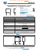
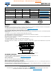
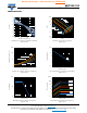
Space Requirements on Printed Circuit Board
The maximum space for length (I
max.
), width (w
max.
) and height (h
max.
) of film capacitors to take in account on the printed circuit
board is shown in the drawings.
• For products with pitch 15 mm, w = l = 0.3 mm; h = 0.1 mm
• For products with 15 mm < pitch 27.5 mm, w = l = 0.5 mm; h = 0.1 mm
Eccentricity defined as in drawing. The maximum eccentricity is smaller than or equal to the lead diameter of the product
concerned.
SOLDERING CONDITIONS
For general soldering conditions and wave soldering profile, we refer to the application note:
“Soldering Guidelines for Film Capacitors”: www.vishay.com/doc?28171
Storage Temperature
T
stg
= -25 °C to +35 °C with RH maximum 75 % without condensation
Ratings and Characteristics Reference Conditions
Unless otherwise specified, all electrical values apply to an ambient temperature of 23 °C ± 1 °C, an atmospheric pressure of
86 kPa to 106 kPa and a relative humidity of 50 % ± 2 %.
For reference testing, a conditioning period shall be applied over 96 h ± 4 h by heating the products in a circulating air oven at
the rated temperature and a relative humidity not exceeding 20 %.
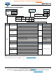
APPROVALS
SAFETY APPROVALS X2 VOLTAGE VALUE FILE NUMBERS LINK
EN 60384-14 (ENEC)
(= IEC 60384-14 ed-4 (2013))
310 V
AC
1 nF to 2.2 µF ENEC16/FI/19/10001 www.vishay.com/doc?28179
UL 60384-14 310 V
AC
1 nF to 2.2 µF E354331
www.vishay.com/doc?28184
CSA-E 384-14 310 V
AC
1 nF to 2.2 µF E354331
CQC GB/T6346.14-2015 310 V
AC
1 nF to 2.2 µF
CQC07001021280 (L) www.vishay.com/doc?28199
CQC04001009262 (F) www.vishay.com/doc?28200
CB test certificate 310 V
AC
1 nF to 2.2 µF FI-39827 www.vishay.com/doc?28175
The ENEC-approval together with the CB-certificate replace all national marks of the following countries (they have already signed the
ENEC-agreement): Austria; Belgium; Czech. Republic; Denmark; Finland; France; Germany; Greece; Hungary; Ireland; Italy; Luxembourg;
Netherlands; Norway; Portugal; Slovenian; Spain; Sweden; Switzerland and United Kingdom.
CBA116
Eccentricity
w
max.
= W + Δ
h
max.
= h + Δ
I
max.
= I + Δ
Seating plane