
User's Manual Part 1
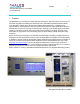
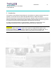

Table of Contents - ii -
®
Affinity LBD-200C-N1 Transmitter
Product Manual
7.1.5 Installation of Power Amplifier Segments .................................................... 37
7.1.6 Installation of Front-End Power Supplies ....................................................38
7.1.7 Installation of UPS System .......................................................................... 40
7.1.8 Installation of Downconverter ...................................................................... 41
8 Site Management System Description ............................................................................ 43
8.1 Status Monitoring and Control System............................................................... 43
9 Satellite Receiver and Remultiplexer Description ........................................................... 44
10 Sirius DVB-H Exciter Description .................................................................................... 45
10.1 Introduction ........................................................................................................ 45
10.1.1 Remote Operation...................................................................................... 52
10.1.2 SNMP Agent and Web Server ................................................................... 52
10.1.3 General Description ...................................................................................55
10.1.4 Main Features ............................................................................................ 55
10.1.5 Sirius Subassembly Description................................................................. 56
10.1.5.1 Digital Board...................................................................................... 56
10.1.5.2 TS Board ........................................................................................... 57
10.1.5.3 Power Supply .................................................................................... 59
10.1.5.4 UHF Synthesizer ............................................................................... 59
10.1.5.5 GPS Receiver.................................................................................... 70
10.1.6 Exciter Rack ............................................................................................... 71
10.1.7 Exciter Connectivity.................................................................................... 72
10.1.8 General Characteristics of Exciter.............................................................. 74
10.1.9 Input/Output Characteristics....................................................................... 75
11 Driver Section Description............................................................................................... 78
11.1 Power Supply Plug-In Module............................................................................ 79
11.1.1 Power Supply Plug-In Module Specifications............................................. 82
11.1.2 Power Supply Module Front and Rear Panel Descriptions ........................ 86
11.2 Upconverter Module........................................................................................... 88
11.2.1 Upconverter Plug-In Module Specifications ............................................... 93
11.2.2 Upconverter Internal Interconnect Drawing................................................ 96
11.2.3 Upconverter RF Block Diagram ................................................................. 97