
Operation Manual Part 1


Digital Liquid Cooled UHF
TV Equipment
Detailed operational description
9946 V1
45321648.01 104 A E
preliminary
33 / 131
Numéro / Number Doc. Rev. Lan
g
u.
16/06/2006
Pa
g
e
Information contained is this document is confidential, is THOMSON property and cannot be disclosed in whatever form without prior written authorization of THOMSON.
2.4.3. Power level bargraphs on PCL
The processing of the command signals which activate the PCL indicator lamps is mainly derived from
data from the "polling of events" system.
"Go home" indicator lamp
The "Go home" indicator lamp is illuminated when one of following events is detected:
♦ the transmitter is in local control mode,
♦ the transmitter is in maintenance mode,
♦ manual on-air/off-air switching mode has been selected,
♦ the PCL screen is unlocked,
♦ the manual exciter changeover mode has been selected (Dual Drive version only),
♦ an exciter changeover has already been carried out (Dual Drive version only),
♦ The reserve exciter is on (Dual Drive version only),
♦ The EXCITER status is NOT CONFORM (The operator chose a MODAP exciter and not a SIRIUS
exciter with the install mode)
♦ The input signal type of SIRIUS is a PRBS.
"On" indicator lamp
The "On" indicator lamp is illuminated when the transmitter is on-air.
"Off" indicator lamp
The "Off" indicator lamp is illuminated when the transmitter is switched off-air.
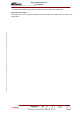
"Alarm" indicator lamp
The "Alarm" indicator lamp has three coloured segments and indicates the status of the RF power
levels based on the measurement from probe in the output of the amplifier channel:
♦ green: the RF power level is satisfactory,
♦ orange: the RF power level lies between the fault threshold and the low alarm threshold; these
levels can be set and monitored in the "RF LEVEL THRESHOLD" window of the PCL,
♦ red: the RF power level is higher than the high alarm threshold or lower than the fault threshold;
these levels can be set and monitored in the "RF LEVEL THRESHOLD" window of the PCL.
Fault
threshold
Low alarm
threshold
High alarm
threshold
0 dB
RED
ORANGE
GREEN
RED
"Unlock" indicator lamp
The "UNLOCK" indicator lamp is illuminated when the PCL screen is unlocked and when the
transmitter is in local control mode.
The "UNLOCK" indicator lamp is extinguished when the PCL screen is locked (disabled) and when the
transmitter is in remote control mode.
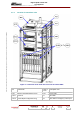
Power level bargraphs on PCL
The illumination of the PCL bargraphs which display the RF power levels, is controlled by the PCL
display card, and varies with the measured values of the RF power levels from the reflectometer
probes on the output of the amplifier channel.