
Operation Manual Part 1


Digital Liquid Cooled UHF
TV Equipment
Description / Test points / Location of units
9946 V1
45321648.01 104 A E
preliminary
38 / 131
Numéro / Number Doc. Rev. Lan
g
u.
16/06/2006
Pa
g
e
Information contained is this document is confidential, is THOMSON property and cannot be disclosed in whatever form without prior written authorization of THOMSON.
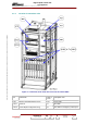
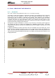
Figure 9 : Localisation of the mains units in rear of the cabinet B860
R1 to R10 Loads network for the F.I.C.S A10 RF Amplifier combiner (FICS)
A10-1 Measuring probes A181 ASI Splitter
A133 Multiplex board FL139 Channel Filter
A115 to A111 Power supply unit A10-2 Harmonic filter