
User's Manual Part 2

Digital Liquid Cooled UHF
TV Equipment
Use of commands and description of indicators
Information contained is this document is confidential, is THOMSON property and cannot be disclosed in whatever form without prior written authorization of THOMSON.
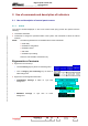
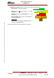
2.1.2. Installation windows
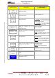
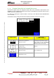
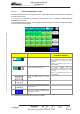
2.1.2.1. "INSTALLATION PARAMETERS Level 1" window
This window appears when the changeover switch SW1 on t
(MODAP version) or on the management system interconnectio witched
so that the dot is visible an
This window is used to change the transmitter configuration param
he exciter/CPU interconnection card
n card (SIRIUS version), is s
d that CPU board is reset.
eters stored in the CPU board.
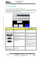
CONTROL KEYS FUNCTIONS SELECTIONS
AVAILABLE/COMMENTS
Selects the transmitter frequency range.
Displays last selection.
VHF I, VHF III, UHF
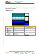
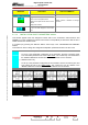
Displays the RF synthesiser frequency value.
Displays last selection.
Pressing this key calls up the "NUMERICAL
VALUE" window in which this frequency can
be changed.
Selects the maximum transmitter power
(Maximum available RF power).
Displays last selection.
Pressing this key calls up the "NUMERICAL
VALUE" window in which this typical
transmitter power can be changed.
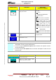
Selects the actual transmitter power
(Calibrated RF power)
Displays last selection.
Power level for which probes and power
output displays (bargraph) of the transmitter
are adjusted.
This level is a reference for the software.
This actual value is associated with the
power levels in % “100”, display in window,
and with the Auto Gain value “128” (Digital
transmitter) of ADAPT exciter.
At any time: CAL Power < MAX Power
Selects the language of the Local Control
Panel windows.
Displays last selection.
FRANCAIS, ENGLISH, ESPAGNOL
9932 V2
45321648.01 108 B E
Checked
42 / 192
Numéro / Number Doc. Rev. Lan
g
u.
27/06/2006
Pa
g
e