
User's Manual Part 5

Digital Liquid Cooled UHF
TV Equipment
Use of commands and description of indicators
Information contained is this document is confidential, is THOMSON property and cannot be disclosed in whatever form without prior written authorization of THOMSON.
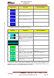
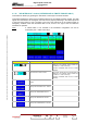
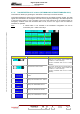
CONTROL KEYS FUNCTIONS DISPLAY/COMMENTS
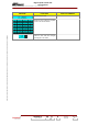
Calls up the "EXCITER Level 1" window.
Calls up the "AMPLIFIERS" window.
Calls up the «INTERLOCK» window
Calls up the "POWER SUPPLY" window.
Calls up the "PA LEVELS" window.
* : Operating only when the
** : Operating only when th plifier.
re is more than one cabinet.
ere is more than one am
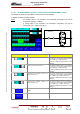
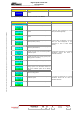
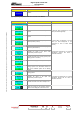
MESSAGE FUNCTIONS DISPLAY/COMMENTS
Gives the window name.
Shows the number of the particular cabinet to w
the data displayed in this window refer.
hich
Shows the number of the particular amplifier to w
the data displayed in this window refer.
hich
Displays the analogue values of the currents in the
transistors T1 to T8.
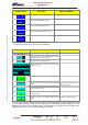
Indicates wheth
er the amplifier is present or missing. PRES / MISSING (1)
Indicates the status of the amplifier
system.
auto diagnostic INTRNL OK / INTRNL FAULT (1)
INTRNL: Internal
Indicates the status of the amplifier Overdrive (RF
current) protection system.
OV CUR OK / OV CUR FAULT (1)
Indicates the status of the amplifier temperature
protection system.
TEMP OK / TEMP FAULT (1)
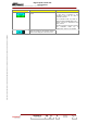
Indicates the status of the amplifier SWR protection
system.
VSWR OK / VSWR FAULT (1)
(1) A fault-free status is displayed in normal video (on black background or green background in case
of colour tactile screen). A faulty status is displayed in reverse video (on white background or red
background in case of colour tactile screen). The transmitter can operate while the status of the
diagnostic systems of one or several RF amplifiers is "FAULT".
9932 V2
45321648.01 108 B E
Checked
158 / 192
Numéro / Number Doc. Rev. Lan
g
u.
27/06/2006
Pa
g
e