
User's Manual Part 5

Digital Liquid Cooled UHF
TV Equipment
Use of commands and description of indicators
9932 V2
45321648.01 108 B E
Checked
185 / 192
Numéro / Number Doc. Rev. Lan
g
u.
27/06/2006
Pa
g
e
Information contained is this document is confidential, is THOMSON property and cannot be disclosed in whatever form without prior written authorization of THOMSON.
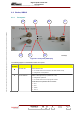
DIAGRAM
REFERENCE
COMPONENT REMARKS
D
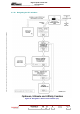
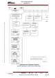
Green OK LED This LED has two functions:
♦ Extinguished: software fault
♦ Lit: indicates that the microprocessor is operating satisfactorily (software)
Note: During the made the powered-on of exciter, the LED “OK” is lit during
approximately 15 seconds indicating the operated of power supply then, put out
(extinct) during approximately 7 seconds indicating the starting-up of the
microprocessor and to end lit. (refer to the diagram below).
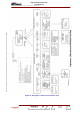
2.2.1.1. Test Points
The RF output signal from the SIRIUS module can be monitored at connector A on the front of the
module.
The RF output signal from the synthesiser unit (LO) can be monitored at connector A1 on the front
panel of the SIRIUS rack.
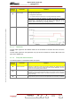
2.2.1.2. Front panel interconnections
The following appear on the SIRIUS module front panel:
DIAGRAM
REFERENCE
COMPONENT REMARKS
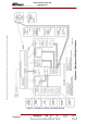
E
COM 1 Connector Reserved for TBM use: Serial link connection (RS232); this enables authorised
personnel to have access to the digital card micro program (Modulator). The user
must not connect anything to this connector.
F
LAN Connector Reserved for TBM use: Ethernet link connection (RJ45) with digital card
(Modulator). This connection is limited to factory use and gives access to high level
functions and fault finding routines in the Sirius module (for use by a technician
using a terminal)
G
PC card reader On the right hand side of the SIRIUS front panel there is a PC card reader which will
accept a memory card on which the exciter parameters can be stored (not available)