
Installation Manual
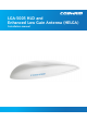


Table Of Contents
- Safety summary
- About This Manual
- Introduction
- Installation
- Maintenance
- Illustrated parts list
- Equipment specifications
- References
- Glossary
- Index

98-152675-A vii
Cobham Public
List of figures
Figure 2-1: LGA-5005..............................................................................................................................................................2-1
Figure 2-2: AVIATOR 200 S with LGA-5005 ................................................................................................................2-3
Figure 3-1: Mounting hole sealing kit..............................................................................................................................3-2
Figure 3-2: Areas where NO sealant is to be applied................................................................................................3-4
Figure 3-3: Breathing/drainage slots, both sides ........................................................................................................3-4
Figure 3-4: Fore/aft of the antenna..................................................................................................................................3-5
Figure 3-5: Base of the antenna.........................................................................................................................................3-8
Figure 3-6: Sealant application to the bolt access holes of the antenna radome...................................... 3-9
Figure 6-1: LGA-5005 – HELGA ..........................................................................................................................................6-1