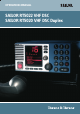
OPERATION MANUAL SAILOR RT5022 VHF DSC SAILOR RT5020 VHF DSC Duplex
Introduction Congratulations on your new SAILOR RT5022/RT5020 VHF. SAILOR marine equipment is specially designed for the extremely rugged conditions on board a ship, based on more than 50 years of experience with all kinds of vessels, from small pleasure crafts, over fishing vessels working under all climatic conditions, to the biggest ships.
Training Information The Thrane & Thrane RT5022/RT5020 VHF radio is designed for “occupational use only” and is also classified as such. It must only be used in the course of employment by individuals aware of both the hazards as well as the way to minimize those hazards. The radio is thus NOT intended for use in an uncontrolled environment by general public. The RT5022/RT5020 has been tested and complies with the FCC RF exposure limits for “Occupational Use Only”.
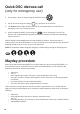
Quick DSC distress call (only for emergency use) 1. If necessary, switch on by pressing the ON/OFF button 2. Lift up the lid covering the orange key and press for 5 seconds. 3. The Alarm indicator light will flash and will be accompanied by a sound. Distress message is sent at the continuous tone. 4. Unless stopped manually, by pressing the key or switching the unit off, the distress call is automatically repeated every 3½-4½ minutes until distress acknowledgment is received.
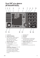
Your VHF at a glance (RT5020/RT5022) 1 2 3 4 5 Alarm Call DW 1W 6 7 8 9 15 16 10 Int US BI Tx SQ Vol 0191 - 05 11 13 14 Loudspeaker Volume level indicator Squelch level indicator Indicator lamps. Condition when lit: 1W: 1 watt transmission mode. Alarm: Alarm call received. Call: DSC call for you received. DW: Dual watch mode 5. Telephone display 6. Indicators.
Contents Introduction .............................................................................................................................. ii About this manual ................................................................................................................ ii Abbreviations used in this manual ...................................................................................... ii Training Information .................................................................................
4 DSC operations in detail ................................................................................................. 15 4.1 MMSI Number ........................................................................................................... 15 4.2 Group MMSI number ................................................................................................ 16 4.3 Differentiating incoming calls by ringing tones ........................................................ 16 4.4 Working channel ..
Radio communication in brief 1.1 Powering VHF The VHF is turned on by a single press on the ON/OFF/Volume button. The VHF is turned off by pressing the ON/OFF/Volume button for 3 seconds. Always indicated by a count down window in the information display, except if the radio is powered down in distress mode. Any connected devices (Alarm Panel, Handset, CUs) will be operational only if the VHF is powered. 1.2 Operating VHF radio communication The VHF is operated by means of a handset.
Basic 6. Switch to the new channel – for example, channel 71 – and begin your conversation. Press PTT only when you are talking. If you are on a simplex channel (in other words, a channel that can carry only one transmission at a time), always say “Over” just before releasing. With duplex channels (ship-shore calls), the conversation can be two-way as with a normal land telephone calls. 1.4 Making a radiotelephone call A radiotelephone call is preferably to be commenced using DSC.
Channel selection Basic 1.8 The system is defaulting to channel 16 after a normal power-on. Channels can be selected using the (increasing to next valid VHF channel) or (decreasing channel). Channels can also be entered using the numeric keypad. The active working channel is always shown in the upper display. 1.9 Dual watch Dual watch is a mode where the priority channel (16) is scanned periodically for a signal while listening on a working channel. Dual watch is activated by pressing the DW button.
Basic When releasing the replay button the replay function will take over the audio system and start to replay the last XX seconds of data received on any channel. The time when the traffic was received and the channel on which it was received is displayed during replay. Volume control can be used on the replay data to adjust sound pressure in audio devices.
2 Basic DSC operations 2.1 Basic When switched on, your VHF automatically monitors channel 70 for incoming DSC calls. Menu operation To operate DSC functionality the menu system is used. The main menu can be activated by pressing . From the main menu all parts of the menu tree can be reached (see chapter: Menu tree). All menus have a unique hierarchical number. The main menu is the only menu which does not have a number.
Basic When you receive a call you can read in the display whether the call is addressed to All Ships, ships in a specific geographic area, a group of ships or to your ship (identified by your MMSI number) as an individual call. If you are busy you can choose to handle the call a little later (e.g. by pressing which will stop the alarm sound. When you are ready to accept the call, lift the handset or press handling the particular call will now appear. Follow the instructions. ), .
Create emergency calls In the category of emergency calls (1.4) you will find the following menu: Transmitting any of these calls should be done with caution. Please make yourself familiar to the common procedures for using these calls. Emergency 1.4 1 Compose Distress 2 Compose Urgency 3 Compose Safety 4 Compose Relays 5 Compose Distress Ack Selecting any of the call types will lead to a call establishing flow with maximum flexibility.
3 Your VHF in detail 3.1 Abnormal power-down If for any reason the main power disappears for a period less than 10 minutes, the VHF will be able to turn itself on when power is resumed (without pressing ON/OFF). Detail If the VHF was abnormally powered down for less than 1 minute, the VHF will start up with the same settings as before the power failure took place (communication channel, volume, squelch settings, etc.).
3.4 Setting channel mode The selected country region is stored during power down sequence. Using the country region BI (Inland waterways) Dual Watch (DW) and scanning mode are not available. 3.5 Private channels Private channels can be defined by using the service interface only (distributor/dealer). Enabled private channels become valid for selection on the front panel. Using the / will simply make the private channel number appear above the highest numeric channel number.
3.7 ATIS (inland waterways only) Detail ATIS is mandatory to use in inland waterways on e.g. the Rhine. ATIS is a digital data stream containing ships call sign coded into a DSC-like message, sent over the voice channel each time the PTT button is released. If PTT is continuously pressed ATIS is automatically sent each 5 minutes. ATIS is enabled automatically when BI is selected in menu (4.4.1). For purpose of operator comfort the received ATIS signal on the active voice channel will be muted.
3.9 Channel scanning Scanning is an extension to the dual watch functionality, by which it is possible to watch multiple channels. It is possible to scan: All channels in a sequence A number of selected channels in a sequence organized into individual 3 scan tables - Scan table A, B and C. The scan type can be selected from the Scanning menu (3). The DW indicator is lit as well (because the priority channel 16 by default is included in any scan table). During the scan “SC” is shown in the upper display.
4 4.1 DSC operations in detail MMSI Number To operate VHF with DSC the equipment needs to be configured with your vessel’s MMSI number. If not configured before installation, the VHF will inform you to program the 9-digit MMSI number at start-up. Detail The vessel’s MMSI number is programmable from the DSC menu (4.5). It can be programmed only once from this menu after which changing of the programmed MMSI will be possible only through the service interface.
4.2 Group MMSI number If your radio is configured as member of a group(s) it will receive group calls to that group. The VHF can be configured to be part of (up to 10) groups. The group MMSI numbers can be programmed from menu 4.5.2. The configured group numbers are shown as a list. You can add a group MMSI number by selecting the list entry and press . Enter a valid group MMSI and press A group number can be changed by selecting the number , edit the number and press OK.
4.4 Working channel A working channel will always be suggested by the system if a ship station or group is called for a routine call. The working channel is suggested by using the following procedure: Detail 1. 2. 3. 4. Select a random channel from the list of simplex channels Scan channel for traffic (open squelch) If the channel is free suggest the channel. If the channel is busy restart from 1. If no channels are found to be free within 1 second no channel is suggested. 4.
• • If the MMSI number is a group number, the group call flow is entered from the window where a channel is selected. If a ship station number MMSI is available, the station call flow is entered from the window where a channel is selected. If the MMSI number is a coast station, the operator will be led to the transmit verification window for a station call. 4.5.1.
See also Section 4.1.2 4.5.4 Editing the contact list Any contacts from the list can be edited using a similar principle as described above using menu item 2.4. Detail 4.5.5 Deleting a Contact Entry Any contact can be deleted from the contact list. If menu 2.5 is selected the contact can be searched for in the list. When found and selected with the contact will be removed from the contact list. 4.
4.6.3 Automatic channel shift The VHF can be set to automatically changing the working channel on receipt of the following call types: • • • Individual radiotelephony acknowledgement with a valid channel information Radiotelephony group calls with valid channel information Radiotelephony all ship safety calls with valid channel information If enabled, a received call will start the (normally) periodic alarm only once. The channel will switch immediately after and the window is closed.
4.7.3 Verification of a DSC call before transmission The final step in each DSC call sequence is the verification window, in which it is possible to verify the call you are about to transmit. The VHF will by default display only information that you could influence in the call setup. Example: Transmit Station Call What is hidden to the user is that calls are formed MMSI: 001234567 according to the specifications ITU R.493-11.
4.8 Radio configuration and settings This section describes the configuration and settings possible to control from the operator front panel and this is not described elsewhere in this manual. If your equipment needs configuration beyond these possibilities, you must call you dealer for special support. Idle display Whenever the radio is left in a state where the information/message display is not in use (pure radio communication mode), the information display will return to idle or stand-by mode.
• Detail • If the product is turned off and on normally using the button, the default language will always be selected, regardless of the language mode before power-off. The following sequence will always put the unit back in default language mode (except when in distress state): Technical abbreviations, such as, the four points of the compass (N, S, E and W), DSC symbol notations (Ack. RQ, Ack. BQ and EOS), etc. is attempted to be maintained as in the default language. 4.8.
5 Errors and warnings Errors and warnings are shown in the display accompanied by the sounds shown in the figure below: TONE SIGNAL 8 sec. Detail 1 sec. ERRORS WARNING & INFO 39718 If you receive an error or warning message you will always be able to shut off the alarm. Press to finish on-going radiotelephony. This procedure will not affect the actual read-out and accept procedure for errors and warnings. Errors and warning messages are shown in the information display.
5.2.1.1 Ship power In some installations ship power might occasionally disappear for a short time, e.g. if switching between land power or generator power. Your equipment will shut down immediately when power is failing. If the power does not arrive within 10 minutes the radio cannot be expected to start up automatically. Detail 5.2.1.2 Fuses If a press on the ON/OFF button does not turn on the radio, and ship power is present, a fuse might need replacement.
5.2.3 GPS Sympton: Position requested. If your radio is connected to a GPS and you receive a request in the display to enter position and time, then it is possibly that the GPS unit is either turned off, broken or disconnected. The GPS is connected on the rear side of the radio, either directly to the option connector or via connection box (see section Interface connections). Please refer to installation section of this manual for connection details. 5.2.
5.2.6 Missing MMSI Symptom: DSC function is not working. If you have powered your VHF for the first time it might not have the MMSI number programmed. You must program the MMSI number before the radio is operational for DSC. Programming is done via menu item 4.5.1 5.2.7 Radio time Symptom: DSC logs are sorted with a wrong time stamp, or radio time is not correct. System The problem with a wrong radio time should occur only if the GPS is not connected in the system.
6 Menu tree This section lists the full menu tree of the VHF. The table describes the un-regretted forward flow that is initiated after selection of certain menu items. Generally, pushing previous window. MENU 1 DSC Call 1.1 1.2 1.3 1.4 Station Call PSTN Call Group Call Em ergency in the menu tree or flow sequence will return to the 1.4.1 Com pose Distres s 1.4.2 Com pose Urgency 1.4.3 Com pose Safety 1.4.4 Com pose Relay 1.4.2.1 1.4.2.2 1.4.3.1 1.4.3.2 1.4.4.
4 Settings 4.4 4.5 Channels 4.4.1 Channel Mode DSC 4.4.2 4.4.3 4.5.1 4.5.2 4.5.3 Channel Info ATIS Call sign MMSI Num ber Group MMSI Special Calls Detail 4.5.4 4.5.5 4.5.6 4.4.1.1 4.4.1.2 4.4.1.3 4.4.1.4 Int US BI CAN O Medical Transports O Ships and Aircrafts Auto Acknow ledgem ent O Auto Channel Sw itch MMSI Sub-address Safety Test O Routine Polling O Safety Position O RT acknow ledgement O Group Calls O All Ships Safety Calls 4.5.6.1 Value of X10 digit 4.5.6.
Optional functional devices The maximum system configuration possible with your VHF installation with VHF is shown in the first part of the installation section. The present chapter will describe the functionality and behaviour of the following optional functional devices: • • • 1 or 2 remote handset control units One alarm panel Printer + LAN interface + printer server 7.1 Semi-functional control unit 7.1.1 1 Controls and indicators 2 3 4 5 6 1. 2. 3. 4. 5. 6. 7 8. 9. 10. 11. 12. 13 14. 15.
7.1.2 Operation The optional handset is intended for VHF radiotelephony only. There will be no DSC functionality supported except for: • • The functionality or lifting of the CU handset follows the default handset on the main radio (see Section DSC receive), when receiving a DSC call. Possibility to mute DSC alarm sound – not to handle the DSC call. 7.1.3 ON/OFF The semi-intelligent handset will always be turned off default after VHF unit is powered.
7.1.6 Squelch The squelch level can be adjusted by using the and buttons. Pressing the buttons will contribute to the global squelch setting on the radio. Squelch indicators on the handset CU and on the main unit will always follow each other regardless of the control input used for adjustment. NOTE: If a channel is reached where the squelch setting was programmed from the main unit, usage of the squelch control will set the level for that particular channel, and reset the squelch programming. 7.1.
alternating ... on errors. ... on alerts. This indication will remain until the DSC call has been handled from the main unit. Though normal radiotelephony calls can be acknowledged from the semi-intelligent handset making the HS hooked to HS un-hooked transition. 7.1.9 Muting alarms If a DSC call is received (distress or routine) the alarm sound is heard as a mixing of the received voice audio in the speakers and earpieces in the system.
7.1.13 Multiple handsets in the system If multiple handsets are connected in the system the following priority is given (to PTT – microphone control) if multiple handsets are lifted: • • The default handset is always given priority if lifted. Any optional handset lifted first takes priority over another optional handset. A warning “OC” is written in the display near any handset (VHF unit or CU) that has lower priority, as soon the prioritized handset is lifted.
8 Maritime Channels 8.
8.
8.
8.
9 Installation 9.1 Mounting possibilities 140 100 VHF with mounting bracket 229 200 256 39835 Mounting option Drilling plan Installation 70 5 80 4xø5.5 16 190 222 39837 Tilting +/- 20° Weight (RT5022): VHF Mounting bracket 4.1 kg 1.0 kg Weight (RT5020): VHF Mounting bracket 4.9 kg 1.
VHF with flush mounting bracket 120 Bracket (Option) 240 min. 100.00 Space for Cable entry 39938 3 20 102 4 pcs. ø5 4 pcs. ø3.5 countersunk for M3 10 228 6 6 20 219 20 108 20 9 Drilling plan Weight: Mounting kit (Part no. 739814) 1 kg WARNING: Only use screws supplied with mounting kit for attaching flush mounting bracket to VHF radio.
Handset for transceiver 75 This hand-set has a hook-on/off functionally, which is activated by a small magnet imbedded in the ceadle. The cradle must be installed as illustrated in order to ensure the hook-on/off functionality of the Handset. min. 200 62 Space for cable and handset cable 135 226 45 Drilling plan 54 * 120 Space for handset access 39655B Installation Weight Handset for transceiver 0.
Semi-functional control unit Drilling plan 25 Space for installing and detaching control unit 2xø5 16 50 83 78 36 100 Length of spiral cord at rest : 380 mm 54 120 min. 200 80 Space for handset access recommended 39654B Weight : Semi-functional control unit Space for cable and handset cable 100 70 9,6 41 100 50 226 100 28 2xø4.5 1.
Connection box 185 225.4 Drilling plan 49 258.4 14.85 4 pcs. ø6 9.75 239 * 50 Mounting * 50 ** min. 100 Installation * 50 * Free space for mounting, ** Free space for cable entry. 39656 Weight Connection box 42 1.
Extension box Drilling plan 49 141.4 14.85 120 160.4 4 pcs. ø6 9.7 122 * 50 Mounting * 50 * 50 ** min. 100 Weight Extension box 0.7 kg * Free space for mounting, ** Free space for cable entry.
LAN box Drilling plan 4xø3.5 26.75 73 126.5 4xø4.5 74.5 37 9 82 100 * 50 Mounting * 50 ** min. 100 * 50 Weight LAN box 0.3 kg * Free space for mounting, ** Free space for cable entry.
9.
Connection box board 639121 EB/CU EXT / CU LS RT50XX SPARC II OPTIONS EXT / CU LS EXT 2 2 2 2 DATA+ 3 AUX2 3 3 3 3 DATA- 4 AUX2 4 4 4 4 TX AF+ 5 AUX1 5 5 5 5 TX AF- AUX1 6 6 6 6 GND 9 INT LSCALL 10 CALL 8 8 7 8 7 8 7 8 X6 VDR- 7 X6 X5 +12.5V 2 INT LS+ X5 X4 1 X3 1 X2 1 X1 VDR+ 7 X4 IF CU IS CONNECTED TO EB/CU TERMINALS THEN REMOVE J1 & J2 FOR X4 AND J3 & J4 FOR X5 X3 1 6 X2 EB/CU X9 X9 RT50XX OPTIONS X1 1 X8 X8 +12.
39701B PL259 RG214 or better RX/TX Antenna RG214 or better Power 12-24V DC Cable L=1.5m furnished with equiptment Option SPARC II bus To LAN Box (optional) Cable part no. 56.111 L=1.2m furnished with LAN Box Ext. speaker (CU) (Optional) 8x2x0.5mm2, max. 20m 8x2x0.5mm2, max. 20m Ext. speaker (VHF) (Optional) Extension Box (Optional) CU 1 (Optional) To Alarm Panel - (if installed) 2x2x0.
Cable connection diagram X3 SPARC II BUS X4 EB/CU X5 RT50XX SPARC II EXT / CU LS CONNECTIONS X6 EB/CU IF CU IS CONNECTED TO EB/CU TERMINALS THEN REMOVE J1 & J2 FOR X4 AND J3 & J4 FOR X5 EXT 1 VDR+ EXT / 1 CU LS +12.5V 2 VDR- 2 DATA+ 3 AUX2 3 DATA- 4 AUX2 4 TX AF+ AUX1 5 TX AF- 6 AUX1 6 GND 7 EXT LS1 7 +12.5V 8 EXT LS1 8 RX AF+ 5 9 CALL 9 RX AF- 10 CALL 10 +12.
Interfaces Options Connections Signal designation Cable Connection Connection p/n 539603 box box 5m In from VHF External conn.
PL259 RG214 or better 39702B RX/TX Antenna RG214 or better Power 12-24V DC Cable part no. 539826 L=1.5m furnished with equiptment SPARC II bus PL259 Handset Ext. speaker (CU1) (Optional) L=3m L=3m CU 2 (Optional) Ext. speaker (VHF) (Optional) Conductor size 8x2x0.5mm2 8x2x0.75mm2 8x2x1mm2 Maximum cable length 20m 30m 40m Power cable p/n 539826, 1.5m 2x4.0mm2 + VDC White 0 VDC Black Power connection 12-24VDC, SPARC II cable length specification 120W min. continuous Ext.
Cable connection diagram X6 : J1 & J2 MOUNTED = EXT LS J1 & J2 NOT MOUNTED = CU LS H2 J1 H3 J2 X4 X5 X6 1 +12.5V EXT/CU LS+ EXT/CU LSX3 1 2 DATA+ 2 3 DATA- 4 TX AF+ 5 TX AF- 5 6 GND 6 CU LS- EXT LS+ EXT LS- X1 X2 3 4 +12.5V X3 X2 X1 7 X6 X5 X4 CU LS+ 7 8 RX AF+ 8 9 RX AF- 9 10 +12.5V10 10 11 LS+ 11 12 LS- 12 12 13 GND 13 13 14 Line out 14 15 Line out 15 CU 14 15 VHF CU/CB H1 CU 2 (Optional) Ext. speaker (CU2) VHF DSC Ext.
9.3 Power supply The VHF should be powered from a separately fused DC-supply of 10.8 - 32VDC and rated at minimum 120W continuous power for installations with RT5022 (Simplex/semi-duplex),and 150W for installations with the RT5020 (Duplex) 9.4 Antenna installation and precautions 9.4.1 Antennas The VHF equipment requires two antennas installed one for the DSC receiver and the other (Primary) for the VHF RX/TX communication.
9.4.3 DSC antenna The positioning of the DSC antennas is less critical in terms of the imposed VSWR and due to the nature of the DSC-signalling. It should be noted however, that the DSC receiver of a VHF is likely to be temporarily blocked in reception due to high signal blocking, if the associated DSC antenna is installed in close vicinity of a RX/TX antenna at the same horizontal level while transmission takes place from this RX/TX antenna. No. 1 VHF RX/TX No. 2 VHF DSC No. 2 VHF RX/TX No.
10 Technical specifications 10.1 General information Channel Tables Private Channels Channel spacing Contact List Scanning Voice replay Automatic squelch Readout 10.2 General DSC facilities DSC operation Installation DSC protocol Navigator interface Symbol error rate Below 1*10-2 Modulation Frequency error Residual modulation 10.3 According to Rec. ITU-R M.541-9 and Rec. ITU-R M.689-2 According to Rec. ITU-R M.
Supply range Transceiver dimensions Transceiver weight 10,8V to 31,2V DC H*W*D 100*200*210 mm 4,1 Kg Receiver Sensitivity for 20 dB SINAD CCITT weighted AF rated Power Internal L.S. Output for External L.S.
more than 43 dB below 0,25 nW more than 74 dB more than 73 dB better than –10 dB more than 74 dB more than 94 dBìV Transmitter RF output power High Low Adjacent channel power Conducted spurious emission Distortion S/N ratio 25W +0dB to –0,5dB 0,85 W +0,5dB to –1dB below 75 dB below 0,25 mW below 3 % better than 46 dB Installation S/N ratio Spurious emission Spurious response rejection Intermodulation response Co- channel rejection Adjacent channel selectivity Blocking level 56 0544
DECLARATION OF CONFORMITY Thrane & Thrane A/S Porsvej 2 9200 Aalborg SV DK-Denmark We as manufacturer herewith declare that the following equipment complies with the specifications of the Marine Equipment Directive 96/98/EC & the amending Directive 2002/75/ EC, A.1/5.1: A.1/5.
Thrane & Thrane A/S • info@thrane.com • www.thrane.