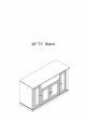
48" TV Stand
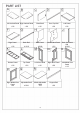
PART LIST A Left Vertical Panel Right Vertical Panel 1 PC 1 PC Fixed Shelf Front Top Rail Left Panel 1 PC 1 PC 1 PC 0 Right Panel Back Rail Back Panel Middle Back Panel 1 PC 2 PCS 2 PCS 1 PC Bottom Panel Top Panel Left Door Panel Right Door Panel 1 PC 1 PC 1 PC 1 PC Right Middle Door Panel 1 PC Adjustable Shelf Middle Adjustable Shelf 1 PC Support Rail 4 PCS 2 N 1 PC Back Horizontal Rail 2 PCS 0 Left Middle Door Panel 1 PC
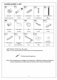
HARDWARE LIST Cam Lock Cam Bolt 20 PCS (Extra 2) ' Wood Dowel Screw 42 PCS 7 PCS (Extra 1) 20 PCS Hex Socket Head Bolt 8 PCS #10 Barrel Nut Shelf Holder Knob Round Head Bolt 8 PCS 20 PCS 4 PCS 4 PCS #12 #11 Double Magnet 1 PC T Round Head Screw 6 PCS (Extra 1) #13 Magnet 2 PCS #14 (Spare Part) Allen Wrench Safety Strap Kit Pin Hinge 1 SET (Extra 4) 1 PC ADDITIONAL TOOLS (Not Provided) Note: It is not recommended to use power tools during assembly.
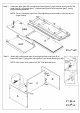
Step 1. Insert cam bolts (part #2) into left vertical panel (part A), right vertical panel (part 8), left panel (part E), right panel (part F), bottom panel (part K) and top panel (part L) using phillips head screwdriver. NOTE: Do not overtighten cam bolts. Stop tightening once threads on cam bolt are no longer visible. A&B E&F #2�x20 Step 2. Attach left vertical panel (part A) and right vertical panel (part B) to fixed shelf (part C) using cam locks (part #1) and wood dowels (part #3).
Step 3. Carefully turn unit upright. Attach front top rail (part D) to assembled unit (parts A & B) using wood dowels (part #3), screws (part #4) and phillips head screwdriver. #3�x2 #4 Step 4. J x2 Carefully turn unit upside down. Attach left panel (part E) to front top rail (part D) using cam lock (part #1) and wood dowel (part #3). NOTE: Cam locks must rotate a full 180 ° . See pictured insert.
Step 5. Attach back rail (part G) to left panel (part E) using cam lock (part #1) and wood dowel (part #3). NOTE: Cam locks must rotate a full 180 ° . See pictured insert. B E A· C turn clockwise to fasten #1 �x1 #3�x1 Step 6. Place back horizontal rails (part J) into back rail (part G) using wood dowels (part #3). Slide back panels (part H) and middle back panel (part I) into the grooves of back horizontal rails (part J) and back rail (part G).
Step 7. Attach right panel (part F) to front top rail (part D) and back rails (part G) using cam locks (part #1) and wood dowels (part #3). Attach magnets (part #10) to front top rail (part D) and double magnet (part #11) to fixed shelf (part C) using round head screws (part #12) and phillips head screwdriver. NOTE: Cam locks must rotate a full 180 ° . See pictured insert. F turn clockwise to fasten 12 C E #1 �x3 #3 6'x3 #10 �x2 #11�x1 Step 8.
Step 9. Attach bottom panel (part K) to assembled unit (parts A, B, E, F & G) using cam lock (part #1), wood dowels (part #3), hex socket head bolts (part #5), barrel nuts (part #6) and allen wrench (part #13). Attach legs using instruction manual and hardware included inside leg packaging. NOTE: Cam locks must rotate a full 180 ° . See pictured insert. point arr lock toward adjacent hole turn clockwise to fasten I I I 1#3 I I I I . F ,,,,✓- --- I I I I ,-, ....... , I I ' , '\ \ \ \ \ I I I
Step 10. Carefully turn unit upright. Attach top panel (part L) to assembled unit (parts A, B, D, E, F & G) using cam locks (part #1 ), wood dowels (part #3), screw (part #4) and phillips head screwdriver. NOTE: Cam locks must rotate a full 180 ° . See pictured insert. turn clockwise to fasten D E .
Step 11. Attach knobs (part #8) to left door panel (part M), right door panel (part N), left middle door panel (part 0) and right middle door panel (part P) using round head bolts (part #9) and phillips head screwdriver. Attach left door panel (part M), right door panel (part N), left middle door panel (part 0) and right middle door panel (part P) by placing bottom pin hinge (pre-installed in door) in the pre-drilled hole of bottom panel (part K).
Step 12. Place shelf holders (part #7) into desired position and then slide adjustable shelves (part Q) and middle adjustable shelf (part R) into place.
C #14 l D8*3/4" Safety Strap Kit 1 SET Wall Anchor 1 PC Washer 2 PCS Short Screw 1 PC E D D8*1-1/2" Long Screw 1 PC Safety Wall Strap 1 PC SAFETY WALL STRAP INSTALLATION Note: It is highly recommended to install this safety strap kit to prevent tipping, damage and/or injury. � 1. Insert short screw (C) through washer (B) and safety wall strap (E) and attach to back of top panel (part L) using phillips head screwdriver. 2. Drill a 11/32" hole where you want to secure the unit.