
Manual


4.2 Installation Tips (Continued)
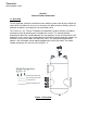
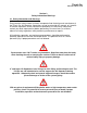
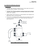
Using the figure below as reference, follow the steps outlined to install piping for the Air
Separator (Figure 4-1, shown with AS Model). Before making any piping connections,
ensure that all piping is clean and free of any foreign material such as debris or scale.
Foreign material in the piping can cause damage to the unit and/or affect the
performance and operation. Manual shutoff valves should be installed
upstream/downstream from all connections to act as an isolation device. These valves
should be in the closed position and remain so until the installation is complete.
Expansion joints and/or flex connectors are recommended to prevent pipe strain caused
by thermal expansion or piping misalignment.
SUPPLY
RETURN
(4"&LARGER)
MODEL720AIRELIMINATOR
SUCTIONDIFFUSER
PUMP
TRI‐FLOWVALVE
BOILER
TANK
DRAIN
DRAIN
ISOLATION
VALVE
AUTOMATIC
FILLVALVE
COLD
WATER
SUPPLY
INLET
OUTLET
ISOLATIONVALVE
FLEXCONNECTOR(S)
AIRSEPARATOR
LIFTLUGS(2)
Figure 4-1 Typical Piping Diagram
1. Connect the supply source to the inlet connection of the Air Separator. Be sure
the upstream manual shutoff valve is in the closed position (Figure 4-1).
2. Connect the suction piping of the pump to the outlet connection of the Air
Separator. Be sure the downstream manual shutoff valve is in the closed position
(Figure 4-1).
Thrush Co.
Manual #9636-1220