Thrush Co. Manual #9636-1400 Pressurizer-VS™ PB-VSI Series Variable Speed Water Booster System Manual # 9636-1400 Rev. B Operation & Maintenance Manual 340 West 8th Street Peru, IN 46970 PH: 765‐472‐3351 FX: 765‐472‐3968 www.thrushco.com COPYRIGHT THRUSH CO., INC.
Thrush Co. Manual #9636-1400 Table of Contents Section No. Description Page No. 1 General Product Information 1 2 Safety Information/Warnings 2 3 Component and Operational Information 3-5 4 Installation, Initial Setup and Operation 6-10 5 Maintenance Information 6 Electrical Drawings 11 12-13 THIS DOCUMENT CONTAINS INFORMATION THAT THRUSH DEEMS CONFIDENTIAL AND PROPRIETARY.
Thrush Co. Manual #9636-1400 Section 1 General Product Information 1.1 Overview The Thrush Pressurizer-VS™ (Figure 1-1) has been carefully assembled and factory tested to provide years of trouble-free service. This manual provides information to allow the installer/operator to install, operate, service and maintain the Pressurizer-VS. In this manual the installer/operator will find multiple Pressurizer-VS models are covered. Visually these different models will look very similar.
Thrush Co. Manual #9636-1400 Section 2 Safety Information/Warnings 2.1 Safety Information Practical safety features have been incorporated into the design and manufacture of the Thrush Pressurizer-VS. If questions are not answered by this manual, or if specific installation, operation, and/or maintenance procedures are not clearly understood, contact your Thrush representative before proceeding. Personnel must, at all times, observe all safety regulations while performing maintenance or repairs.
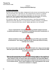
Thrush Co. Manual #9636-1400 Section 3 Component Identification and Information 3.1 Component Identification The following paragraphs contain functional descriptions for each of the major components of a Thrush Pressurizer-VS. This manual provides information for multiple Pressurizer-VS models. All the components listed have the same functional purpose throughout each model. In Figure 3-1, the Pressurizer-VS illustrates available optional equipment.
Thrush Co. Manual #9636-1400 3.1.1 TV2g Pump The TV2g series pump utilized on the Pressurizer-VS is designed to mount in-line to reduce the overall footprint of the system. The top pull out feature allows maintenance of the pump mechanical seal without disturbing the piping. 3.1.2 Hydro-Pneumatic Tank The hydro-pneumatic tank is a pre-pressurized tank that enables the system to react instantaneously upon demand.
Thrush Co. Manual #9636-1400 3.1.7 Pressure Gauge Pressure gauges are located on the suction (inlet) and discharge (outlet) sides of the pump. These gauges allow the user to monitor activity of the piping system and troubleshoot potential problems. Discharge pressure – suction pressure = total system boost. 3.2 Optional Equipment Although the standard Pressurizer-VS was designed to meet customer requirements, the need for optional equipment may arise.
Thrush Co. Manual #9636-1400 Section 4 Installation, Initial Start-Up and Operation 4.1 Piping Installation The following procedures are to aid the operator in installing, operating and maintaining the Thrush Pressurizer-VS. All procedures are to be performed by experienced, trained, and certified personnel only. Before the unit is installed, the unit should be visually inspected for any irregularities that may have occurred during shipping. If any parts are missing or damaged, contact your representative.
Thrush Co. Manual #9636-1400 4.1 Piping Installation (Continued) 4. Suction piping directly affects the overall operation of the Pressurizer-VS and is critical to performance. The pipe size should be sized to allow adequate flow at a minimal head loss, and be, at minimum, the same size as the Pressurizer-VS connections. The use of fittings (elbows, tees and couplings) should be kept to a minimum as well. The same considerations should be applied when sizing and laying out the discharge piping. 5.
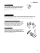
Thrush Co. Manual #9636-1400 4.3 Initial Startup Procedure The Standard Pressurizer-VS is equipped with an ABB Drive (Figure 4-3-1), also available is an optional Yaskawa Drive (Figure 4-3-2). Displays and controls for each controller are described below.
Thrush Co. Manual #9636-1400 4.3 Initial Startup Procedure (Continued) Read and fully understand Safety Information/Warnings in Section 2 before continuing 1. Never work on the VFD, wiring, motor or other component when electrical power is energized. Disconnect the power and verify that power to the Pressurizer-VS is off. 2. Assure that the suction and discharge isolation valves are closed. 3. Verify that the tank pre-charge pressure is set per Figure 4-4.
Thrush Co. Manual #9636-1400 4.4 Operation The Pressurizer-VS was designed to accommodate your booster application needs. Depending on the model, water pressure can be boosted from 30-80 psi with flow rates up to 200 GPM.
Thrush Co. Manual #9636-1400 Section 5 Maintenance Information 5.1 Maintenance Information The information in this section details the proper maintenance procedures for the components of the Pressurizer-VS. Because this manual serves multiple models of Pressurizer-VS, the information may be general in some instances. If there are any questions concerning maintenance procedures that are not clearly explained in this manual, contact your representative.
Thrush Co. Manual #9636-1400 Section 6 Electrical Drawings 6.1 Electrical Drawings (for use with ABB Drive) Before installation and or servicing electricity to the VFD, refer to the ABB user manual supplied with the Pressurizer-VS for all safety warnings and cautions. The figures in this section illustrate factory wiring for reference in the event a component or the wiring needs replaced on the Pressurizer-VS. Figure 6-1-1 illustrates incoming power and ground connections to the VFD.
Thrush Co. Manual #9636-1400 6.2 Electrical Drawings (for use with Yaskawa Drive) Before installation and or servicing electricity to the VFD, refer to the Yaskawa user manual supplied with the Pressurizer-VS for all safety warnings and cautions. The figures in this section illustrate factory wiring for reference in the event a component or the wiring needs replaced on the Pressurizer-VS. Figure 6-2-1 illustrates incoming power and ground connections to the VFD.