Europe, Middle East ENGLISH FRANÇAIS DEUTSCH NEDERLANDS ITALIANO ESPAÑOL PORTUGUÊS РУССКИЙ ΕΛΛΗΝΙΚΑ TÜRKÇE POLSKI اﻟﻌﺮﺑﻴﺔ North America/ Norteamérica ENGLISH FRANÇAIS ESPAÑOL Latin America/ América Latina ENGLISH ESPAÑOL PORTUGUÊS Asia Pacific 日本語 한국어 ENGLISH 中文 ENGLISH
FOR PLAYSTATION®3 – PLAYSTATION®4 User Manual WARNING: To ensure that your T300 RS racing wheel functions correctly with games for PlayStation®3 or PlayStation®4, you may be required to install the games’ automatic updates (available when your console is connected to the Internet).
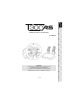
TECHNICAL FEATURES 1 2 3 4 5 6 7 SELECT/START buttons on PS3™ and SHARE/OPTIONS on PS4™ 8 PS button 9 Large threaded hole (for attachment system and fastening screw) 10 Attachment system 11 Metal fastening screw T300 RS base PS wheel 2 sequential paddle shifters (Up & Down) Directional buttons PS4™ or PS3™ USB sliding switch MODE button + red/green indicator light 12 Thrustmaster Quick Release 13 L3/R3 buttons 14 Power supply connector (type A or B) (varies from one country to another) 15 Racing wheel
PLUGGING THE RACING WHEEL INTO AN ELECTRICAL OUTLET: PLEASE READ BEFORE PROCEEDING! Your racing wheel’s power supply varies according to the country where you purchased your device. The power supply can be: Internal, with: * a power supply unit located directly inside the racing wheel’s base, with a type A connector. * a 220-240 V power supply cable. = compatible only with 220-240 V electrical power.
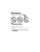
WARNINGS Before using this product, please read this manual carefully and save it for later reference. * * * * * * * * * * * * Warning – Electrical shock Keep the product in a dry location and do not expose it to dust or sunlight. Do not twist or pull on the connectors and cables. Do not spill any liquid on the product or its connectors. Do not short-circuit the product. Never dismantle the product; do not throw it onto a fire and do not expose it to high temperatures.
Warning – Injuries due to Force Feedback and repeated movements (continued) * If the symptoms or pain indicated above persist when you start playing again, stop playing and consult your doctor. * Keep out of children’s reach. * During gameplay, always leave both hands correctly positioned on the wheel without letting it go completely. * During gameplay, never place your hands or your fingers under the pedals or anywhere near the pedal set.
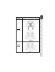
Warning – Pedal set pinch hazard when playing * * * * Keep the pedal set out of children’s reach. During gameplay, never place your fingers on or anywhere near the sides of the pedals. During gameplay, never place your fingers on or anywhere near the pedals’ rear base. During gameplay, never place your fingers on or anywhere near the pedals’ front base. NEVER NEVER NEVER Warning – Pedal set pinch hazard when not playing * Store the pedal set in a safe place, and keep it out of children’s reach.
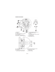
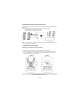
INSTALLING THE RACING WHEEL ON ITS BASE Align the connector positions using the arrows: Base (1) connector: Arrow pointing upwards Racing wheel (2) connector: Arrow pointing upwards Once the connectors are correctly positioned, simply rotate the Thrustmaster Quick Release (12) device’s ring counterclockwise, while holding the racing wheel (2) in position. Then, tighten the ring as much as you can: to do so, hold the ring in position and rotate the racing wheel clockwise.
ADJUSTING THE PEDALS’ HEIGHT AND SPACING Using a Phillips screwdriver (not included), remove the 2 attachment screws holding the pedal heads to the pedal arms. Next, adjust the pedal heads’ height and spacing to suit your preferred driving style: - 6 different positions are available for the gas pedal. - 6 different positions are available for the brake pedal. Once you are happy with the height and spacing, replace and re-tighten the 2 attachment screws holding the pedal heads to the pedal arms.
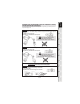
ATTACHMENT / REMOVAL DIRECTION To tighten: Turn the screw counterclockwise To release: Turn the screw clockwise 9/18
Attaching the racing wheel’s base to a cockpit 1. Place the racing wheel’s base on the cockpit shelf. 2. Drive two M6 screws (not included) through the cockpit shelf, then feed them into the two small screw threads located on the underside of the racing wheel. Important: The length of the two M6 screws must not exceed the thickness of the shelf + 12 mm; longer screws could cause damage to internal components located in the racing wheel’s base. 3.
SETTING UP THE PLAYSTATION®4 RACING WHEEL FOR PLAYSTATION®3 OR 1. Connect the pedal set to the connector (17) located at the back of the racing wheel's base. 2. Connect the power supply cable to the connector (14) located at the back of the racing wheel's base. 3. Plug the power supply cable into an electrical outlet with the same voltage specifications. For more information about this, please refer to the PLUGGING THE RACING WHEEL INTO AN ELECTRICAL OUTLET section, on page 3 in this manual. 4.
SETTING UP THE RACING WHEEL FOR PC Important note: On PC, the USB sliding switch (5) on the racing wheel’s base must always be set to the PS3™ position. 1. Go to http://ts.thrustmaster.com to download the drivers and the Force Feedback software for PC. In the Updates and Downloads section, click PC / Wheels / T300 RS, then select Drivers. 2.
PC MAPPING 13/18
AUTOMATIC RACING WHEEL AND PEDAL SET CALIBRATION The wheel automatically self-calibrates when you plug the racing wheel into an electrical outlet and connect the racing wheel’s USB connector to the console. During this phase, the racing wheel will rotate quickly towards the left and the right, covering a 900 degree angle, before stopping at the centre. WARNING: Never touch the racing wheel during the self-calibration phase! (This could result in improper calibration and/or personal injuries.
MODE BUTTON AND INDICATOR LIGHT (6) MODE button for the pedal set The pedal set included with the T300 RS features 2 pedals. When using this pedal set, make sure that the indicator light remains red, or else the gas pedal will not function properly. The T300 RS is also compatible with Thrustmaster pedal sets featuring 3 pedals (sold separately); these allow you to electronically swap the accelerator and clutch pedals. To do so, simply press the MODE button (6) for 2 seconds.
TECHNICAL SUPPORT If you encounter a problem with your product, please go to http://ts.thrustmaster.com and click Technical Support. From there you will be able to access various utilities (Frequently Asked Questions (FAQ), the latest versions of drivers and software) that may help to resolve your problem.
Consumer warranty information Worldwide, Guillemot Corporation S.A. (hereinafter “Guillemot”) warrants to the consumer that this Thrustmaster product shall be free from defects in materials and workmanship, for a warranty period which corresponds to the time limit to bring an action for conformity with respect to this product. In the countries of the European Union, this corresponds to a period of two (2) years from delivery of the Thrustmaster product.