
Data Sheet
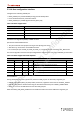
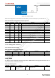
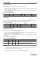
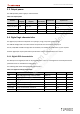
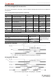
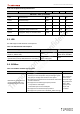
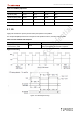
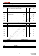
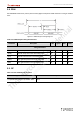
Table Of Contents
- 5.User Manual
- Revision History
- Table List
- About This Document
- Table of Contents
- Chapter 1. Overview
- Chapter 2. Interfaces Description
- 2.1. Interfaces parameter definitions
- 2.2. Pin description
- 2.3. Interfaces detail description
- 2.3.1. Power supply interface
- 2.3.2. RGMII interfaces
- 2.3.3. SPDIF interface
- 2.3.4. Audio interface
- 2.3.5. USB interface
- 2.3.6. PCIe interface
- 2.3.7. MIPI DSI interface
- 2.3.8. HDMI interface
- 2.3.9. JTAG interface
- 2.3.10. SDIO interface
- 2.3.11. BLSP interface
- 2.3.12. Power on interface
- 2.3.13. Reset interface
- 2.3.14. Boot configuration interface
- 2.3.15. Debug UART interface
- 2.3.16. PWM
- 2.3.17. Sleep clock
- 2.3.18. SPMI
- 2.3.19. Antenna interface
- Chapter 3. Electrical Characteristics
- Appendix 1. Notices
- Appendix 2. Trademarks
- 5.User Manual_ Warning

Thundercomm TurboX C40x SOM Datasheet
- 32 -
Table 3-11. SLIMbus frequencies
SLIMbus SVS Normal Turbo Units
Slimbus1 (IFM) 24.57 24.57 24.57 MHz
Slimbus2 (QCA) (IFM) 24.57 24.57 24.57 MHz
Slimbus1 (XFM) 23.1 23.1 23.1 MHz
Slimbus2 (XFM) 22.4 22.4 22.4 MHz
3.7. I2S
Legacy I2S interfaces for primary and secondary microphones and speakers.
The multiple I2S (MI2S) interface for microphone and speaker functions, including audio for HDMI.
Table 3-12. I2S standards and exceptions
Applicable standard Feature exceptions Device variations
Philips I2S Bus Specifications
revised June 5, 1996
None
Timing – When an external SCK clock is used, a
duty cycle between 45% to 55% is required.
High-level I2S timing
Figure 3-3. I2S Interface Timing
nicholas.wang_thundercomm.com
2022-07-21 2:34:47 AM CST