
Data Sheet
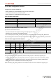
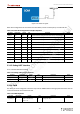
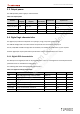
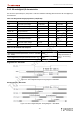
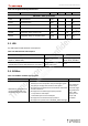
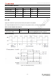
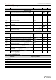
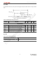
Table Of Contents
- 5.User Manual
- Revision History
- Table List
- About This Document
- Table of Contents
- Chapter 1. Overview
- Chapter 2. Interfaces Description
- 2.1. Interfaces parameter definitions
- 2.2. Pin description
- 2.3. Interfaces detail description
- 2.3.1. Power supply interface
- 2.3.2. RGMII interfaces
- 2.3.3. SPDIF interface
- 2.3.4. Audio interface
- 2.3.5. USB interface
- 2.3.6. PCIe interface
- 2.3.7. MIPI DSI interface
- 2.3.8. HDMI interface
- 2.3.9. JTAG interface
- 2.3.10. SDIO interface
- 2.3.11. BLSP interface
- 2.3.12. Power on interface
- 2.3.13. Reset interface
- 2.3.14. Boot configuration interface
- 2.3.15. Debug UART interface
- 2.3.16. PWM
- 2.3.17. Sleep clock
- 2.3.18. SPMI
- 2.3.19. Antenna interface
- Chapter 3. Electrical Characteristics
- Appendix 1. Notices
- Appendix 2. Trademarks
- 5.User Manual_ Warning

Thundercomm TurboX C40x SOM Datasheet
- 33 -
Table 3-13. I2S interface timing characteristics
Parameter Description Min Typical Max Units
Using internal SCK
F Frequency. Load capacitance is between 10 and 40pF. 12.288 MHz
T Clock period. Load capacitance is between 10 and 40pF. 81.380 - - ns
t(HC) Clock high. Load capacitance is between 10 and 40pF. 0.45 x T 0.55 x T ns
t(LC) Clock low. Load capacitance is between 10 and 40pF. 0.45 x T 0.55 x T ns
t(sr)
SD and WS input setup time. Load capacitance is
between 10 and 40pF.
16.276 - - ns
t(hr)
SD and WS input hold time. Load capacitance is between
10 and 40pF.
0 - - ns
t(dtr)
SD and WS output delay. Load capacitance is between
10 and 40pF.
- - 65.100 ns
t(htr)
SD and WS output hold time. Load capacitance is
between 10 and 40pF.
0 - - ns
Using external SCK
F Frequency. Load capacitance is between 10 and 40pF. 12.288 MHz
T Clock period. Load capacitance is between 10 and 40pF. 81.380 - - ns
t(HC) Clock high. Load capacitance is between 10 and 40pF. 0.45 x T 0.55 x T ns
t(LC) Clock low. Load capacitance is between 10 and 40pF. 0.45 x T 0.55 x T ns
t(sr)
SD and WS input setup time. Load capacitance is
between 10 and 40pF.
16.276 - - ns
t(hr)
SD and WS input hold time. Load capacitance is between
10 and 40pF.
0 - - ns
t(dtr)
SD and WS output delay. Load capacitance is between
10 and 40pF.
- - 65.100 ns
t(htr)
SD and WS output hold time. Load capacitance is
between 10 and 40pF.
0 - - ns
Table 3-14. I2S interface frequencies
Interface Frequency achieved
I2S1 24.57 MHz
I2S2 12.288 MHz
I2S3A 12.288 MHz
I2S3B 12.288 MHz
I2S5 24.57 MHz
I2S6 12.288 MHz
nicholas.wang_thundercomm.com
2022-07-21 2:34:47 AM CST