
User Manual


Page |
9
USB connector : To the computor for downloading data
from the internal memory.
Lemo 5pin connector : To G2100 COM2
Dsub 9pin RS232/Serial connector: To the Data cable.
(56021-Z212)
Data Cable for External
Radio & Power cable for
G2100
Alligator clip type terminal: To the external battery
+9...+15 VDC.
ODU 8pin connector: To the external radio.Data Cable for External
Radio
ODU 4pin connector: To the external radio.
Power Cable for Satelline-
EASy Pro 35W Radio
Alligator clip type terminal: To the external power
+9...+16 VDC.
2.1.4. Using the G2100
For problem free operation, the user should read this G2100 User Manual thoroughly before first
use of the G2100.
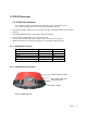
2.1.5. G2100 Front Panel
BT: LED for Bluetooth
RTK: LED for RTK
PWR: LED for Power
WR: LED for Internal Data Logging
STA: LED for Nos. of GNSS Satellites
Fn: Function Key
PWR: Power Key
Figure 5: G2100 Front Panel Label
2.1.6. Front Panel Description
Table 2: LED Operation
Mode Normal mode Connection mode Setting mode
Operation to
change the
mode
---
Press Fn key (3Sec)
Press PWR & Fn key
at once (3Sec)
Blue
ON: Established device
Communication
OFF: Idle for device bonding
ON:GSM/GPRS ON:STATIC
Yellow
ON(Flashing): RTK Base Receiving
correction data
OFF:No RTK corrections
ON: Internal Radio ON:RTK Base