Please read the instructions before installation and use.
Preface The JB-TB-TC5126W wireless intelligent fire alarm control panel is a new generation of intelligent integrated wireless fire alarm control panel designed and developed under our company's full investigation of the fire protection market demand, summarizing the company's fire engineering experience in the fire protection industry for many years, and fully meeting the requirements of GB4717-2005 fire alarm control panel, GA1151-2014 General Requirements for Wireless Communication Function of Fire Alarm
1. General Chapter 1 JB-TB-TC5126W Wireless Intelligent Fire Alarm Control Panel Introduction 1.1 System introduction JB-TB-TC5126W Wireless Intelligent Fire Alarm Control Panel (hereinafter referred to as control panel) is a new generation of wireless fire alarm control panel introduced by Yingkou Tiancheng Fire Protection Equipment Co., Ltd., which can be used together with other related products of our company.
history, fault history and other history each have a capacity of 1000. It CAN support CAN bus and network with other fire alarm control panels of our company. Wireless 470MHZ communication mode is adopted to connect with the detectors matched with the system. Executive standard: GB4717-2005 fire alarm control panel GA 1151-2014 general requirements for wireless communication function of fire alarm system GB16806-2006 fire linkage control system 1.
Backup power supply: lead-acid battery 12V/3.3Ah 2 batteries. 1.4.2 Operating environment Temperature: -10℃ ~+55℃. Humidity: ≤95%, non-condensing. 1.4.3 Equipment capacity Number of loops: two wireless loops. Number of components in each loop: 32 points. Number of network segments: 29. 1.4.4 wire system requirements CAN bus: RVS twisted pair with cross-sectional area ≥ 1.0mm. 1.4.5 Radio frequency parameters Transmit power: < 20dBm Communication distance: ≤50m Frequency band: 470MHz 1.4.
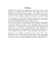
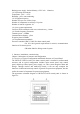
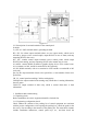
Figure 2-1 The above picture shows: (1) control panel part (2) loop control panel part (18 points) (3) direct control panel (6 loops) 2.2 Description of control panel The structural schematic diagram of fire alarm control panel \ fire linkage control panel is shown in Figure 2-2: it consists of three parts: display operation area, loop control area and multi-loop control area, among which the multi-loop control area is shown in the corresponding instructions.
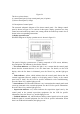
· Main power operating indicator: green, which lights when the control panel is powered by AC220V power supply. · Standby power operating light: green. When the control panel is powered by standby power, this light will light up. ·Disable indicator: yellow. When an external device (detector, module, etc.) fails, it can be disabled. After repair or replacement, the device can be restored by using the function of removing disable. This indicator comes on when disable equipment exists.
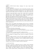
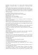
Figure 2-3 The loop control panel has 18 manual fire starting points, and each starting point has a key, two indicators and a label. Among them, the key is the start/stop control key. If the control key of a certain unit is pressed, the control command will be sent out. When the start-up state of the equipment is received, the command light of the unit will light up (red). If the controlled equipment starts and sends out a feedback signal, the answer indicator will light up (red).
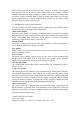
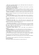
Figure 2-4 2.3.2 Description of external terminals of the control panel In which: L, n, PE: AC 220V terminal and AC grounding terminal. HJ+, HJ-: fire alarm output terminals (there are two output modes, which can be selected by jumper. Active control output, output DC24V in case of alarm, and stop outputting DC24V after reset). SG+, SG-: sounder control output terminals (active control points, which output DC24V when starting, and stop outputting DC24V after manual stop or reset).
appearance of the control panel if it is correct. Please contact the after-sales department of Tiancheng Company if any nonconformity is found during various checks. 3.1.2 Check the internal configuration and connection status of the control panel Check whether the connections among the components in the control panel are normal.
external linkage equipment. 3.6.8 Train operators in correct operation and use methods, and immediately put them into normal operation after acceptance. 4. System application Chapter 4 General user instructions 4.1 Power-on, Power-off and Self-test When the commissioning work is completed, the user can start the equipment in the following order: ·Turn on the power of related equipment. ·Turn on the main and standby switches that control the power supply.
and the LCD screen displays a screen asking for password input. At this time, enter the correct user password and press the "Confirm" key to enter the corresponding operation level and obtain the corresponding authority, and automatically exit to the first level without operation for 30S. 4.3 Device Registration and Registration Check 4.3.1 Device registration Press the "Menu" key to enter the main menu, then press the number 5 to enter "5. System Settings" → "4.
Figure 4-3 4.4 Real-time information display and history record information display 4.4.1 Information display When any information such as fire alarm, linkage, supervision, fault and others exists in the system, the system will display this information; If there is more than one information in the system, the system will display it according to the priority of fire alarm > linkage > supervision > fault > isolation. Figure 4-4 Figure 4-4 shows the display page of fire alarm and linkage information. 4.
whether there is a fire. If it is a false alarm, find out the reason and handle it as appropriate; If it is confirmed that a fire brEntere out, the fire fighting work should be organized immediately. 4.6.2 General handling methods of faults Faults can generally be divided into two categories, one is the main control system fault, such as main and standby power fault, bus fault, etc.; The other is on-site equipment fault, such as detector fault, module fault, etc.
control panel is in the key locking state, enter the user password to unlock it), and the screen display is shown in Figure 4-11 and Figure 4-12. Enter the circuit and address of the equipment to be started or stopped. Press the "Confirm" key, and the control panel issues a command to start or stop the equipment. Figure 4-11 Figure 4-12 4.8.
stopped state. 4.9 Automatic linkage control of bus controlled equipment 4.9.1 Conditions for realizing automatic linkage Only when the control panel is in the state of "automatic permission", can the automatic linkage start command be issued. When someone is on duty, the bus equipment should be started manually as much as possible. 4.9.
Enter "User Settings" → "4. Print Settings", and the LCD screen displays the Settings Print Settings menu (as shown in Figure 5-2): Figure 5-2 In the "printing off" state, the system does not print any information. In the "printing on" state, the printer prints new information in the system immediately. 5.3 Equipment Definition Enter "System Settings" → "1. Loop Component Settings". Figure 5-3 5.3.
modules, etc. All these external devices need to be coded. The codes of these devices include the original address and the on-site code. "Channel" is filled with "01" by default for equipment without channel. The "user secondary number" consists of eight digits from 0 to 9, which is a group of numbers defined artificially to express the specific on-site environment where the equipment is located.
relationship on the bus panel. After setting, press the "Cancel" key to exit the setting. When the linkage module is connected to the local machine, fill in 000, and when the linkage module is connected to other machines, fill in the number of the control panel where the module is located. 5.4.3 Definition example of direct control panel Enter "System Settings" → "3. Direct control panel Settings". Figure 5-5 Enter the key number of the direct control panel and the corresponding setting information.
If this method is used, the network segments are not enough and can be recycled. Ensure that the network segments between adjacent control panels are separated by more than 5 network segments, and the greater the interval, the smaller the mutual interference. Then enter the registration, and press the "Up and Down" button to select the sensitivity for sensing equipment. 5.
Example: y (01010001011) = (01010 * * * 002) _ 1+(01010 * * * 004) _ 1 It means that when any one of the smEntere sensors with the first five digits of the secondary code 01010 gives an alarm, or any one of the manual reports with the first five digits of the secondary code 01010 gives an alarm, the audible and visual alarm No.01010001 starts immediately.
selected state. Figure 5-8 Note: Manual mode refers to the operation of starting and stopping the linkage equipment through the main control keyboard or bus control panel, and the manual allowed status is displayed in the status bar at the bottom of the screen. Automatic mode refers to the linkage operation automatically performed by the system after the linkage conditions are met. 6. Direct control panel 6.
6.4 Structural Features of Direct system 6.4.1. Description of panel (1) Fault indicator: yellow. When the external control line of this road is short-circuited or open-circuited, the light will come on. (2) Start indicator: red, which lights up after the control command is issued. (3) Feedback indicator: red. When the controlled equipment is in response to the command, the feedback indicator lights up. 6.4.2. Description of direct control panel The structural diagram of the output part of 6.4.2.
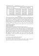
4 5 6 7 8 C. Loss or damage of the relevant connectors battery C. after starting up for more than 8 hours under AC power supply, replace the battery if the fault cannot be eliminated. can not register communication line Check the power line and the external connection error or bad communication line of the fire display panel display panel do not print A. Not set to print on A. Reset the settings B. Bad connection of B. Check and connect well printer cable C. Change the printer C.
Appendix I Technical Indicators Control panel capacity: Up to 2 wireless circuits with 32 address points per circuit. Up to 1 multi-wire control panel, 6 groups in total. Up to 1 bus control panel, 18 groups in total. Wiring system: Wiring system Circuit Distance RS485bus two-core disable < 500m wire RV Multi-loop ≥1.0mm2 < 1.