
Technical Specifications
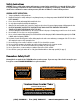

Tie Down Engineering • 255 Villanova Drive SW • Atlanta, Georgia 30336
9
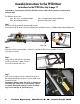
Engine Base
Assembly Arm
Engine Base
Assembly Arm
Retaining
Rings
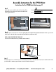
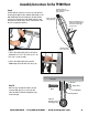
Step 12
Mount the motor assembly to the base unit; from behind the hoist; the foot pad of the motor base slides under the track base section,
while “hanging” the motor base. The motor assembly arms must fit outside the two retainer rings shown above.
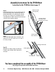
Step 11
See “Raising Hoist” instructions (page 7) for proper positioning/placement of base at the set at job site.
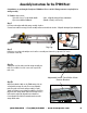
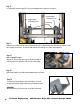
Step 13
Before starting the engine...
Attach the “V” belt to the large pulley (next to cable drum assembly on
track base), then to the small pulley on the motor base (shown right).
Step 14
Slide the brake handle over the brake arm and tighten thumb screw provided.
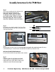
Step 15
If needed, remove plywood brackets and rotate 90 degrees. Secure the
two plywood/rolled goods brackets with push pins provided (shown right).
IMPORTANT:
When lifting panel goods, panels must be secured with tie down straps.