Platform Hoist Owners Manual Color Logo use on white background only Red: 0-100-100-0 Blue: PMS 293 100-56-0-0 Updated: 3/23/15 Black Logo use on white background only TP250 White Logo use on black background only 250 lb. Capacity TP400 400 lb. Capacity Instructions #08238 TIE DOWN ENGINEERING • 255 Villanova Drive SW • Atlanta, GA 30336 www.tiedown.com (404) 344-0000 Fax (404) 349-0401 E1399/Rev. 032315 For the Most Up to Date Information and Instructions, Visit the TranzSporter Web Site at www.
Congratulations on your Purchase of the TranzSporter Lift Hoist. The TranzSporter Lift Hoist was designed to provide safe and continuous operation. Features Include... • • • • • • • • • • • • Collapsible carriage comes with track cam followers for better tracking and handling. Aluminum deck and flap for lighter weight and longer life. Rolled goods/plywood bracket comes with unit and pins into carriage. Motor base is manufactured using laser cut steel tubing for extra strength and durability.
Safety Instructions CAUTION: Please read the safety warnings and Instructions contained in this manual before operating the lift hoist. Failure to obey the warnings contained herein could result in damage to the equipment, personal injury, or death, this information should not be a substitute for routine accident prevention, but rather an addition to routine accident prevention. GENERAL SAFETY INSTRUCTIONS: 15642-2 1. Transport and handle your lift hoist with care. 2.
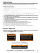
Assembly Instructions for the TP250 Hoist Instructions for the TP400 Hoist skip to page 11 Congratulations on purchasing the TranzSporter TP250 Hoist. Please read the following instructions completely before starting assembly. The TP250 Hoist ships in 4 units: 1) Box - Base Section, Top Cap & Brake Handle 3) Box - Motor Weldment & Manuals 2) Box - Collapsible Carriage & Plywood Attachments 4) Bundle of Tracks (3 -8 ft.
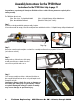
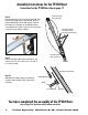
Assembly Instructions for the TP250 Hoist Instructions for the TP400 Hoist skip to page 11 Step 5 Lay one track section on a flat floor with the “front” side up. This is determined by the space between the track cross bar and the track section edge as shown above. Front Back Picture 5 Picture 4 Step 6 Attach splice plates to the bottom section of the track. Splice plates are mounted on the outside track section.
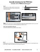
Assembly Instructions for the TP250 Hoist Instructions for the TP400 Hoist skip to page 11 Step 8 Feed end cable through pully From the back side of the hoist, remove the end of the cable from the drum (shown right). It helps to attach the brake handle, use the brake handle back releases the brake drum. The cable will then easily un-spool. Staying on the outside (back) of the base section and track section, take the cable to the top of the last track section where the top cap pulley is attached.
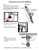
Assembly Instructions for the TP400 Hoist Congratulations on purchasing the TranzSporter TP400 Hoist. Please read the following instructions completely before starting assembly. The TP400 Hoist ships in 4 units: 1) Box - Base Section, Top Cap & Brake Handle 3) Box - Motor Weldment & Manuals 2) Box - Collapsible Carriage & Plywood Attachments 4) Bundle of Tracks (3 -8 ft. Sections) Step 1 If you have not already assembled the carriage assembly: Stop Now.
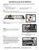
Assembly Instructions for the TP400 Hoist Step 4 “Roll”carriage assembly onto the base. At this time lock the base in place using the Safety Pin as shown. Important: Always check for wear or damage to the safety pin cable/ pull ring assembly. Failure to replace damaged safety pin cable assembly may cause damage or personal injury. Step 5 Lay one track section on a flat floor with the “front” side up. This is determined by the space between the track cross bar and the track section edge as shown above.
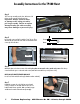
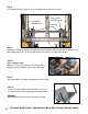
Assembly Instructions for the TP400 Hoist Attach cable to the back side of the pully bracket Step 8 From the back side of the hoist, remove the end of the cable from the drum (shown right). It helps to attach the brake handle, use the brake handle back releases the brake drum. The cable will then easily un-spool. Staying on the outside (back) of the base section and track section, take the cable to the top of the last track section where the top cap pulley is attached.
Step 11 See “Raising Hoist” instructions (page 7) for proper positioning/placement of base at the set at job site. Engine Base Assembly Arm Engine Base Assembly Arm Retaining Rings Step 12 Mount the motor assembly to the base unit; from behind the hoist; the foot pad of the motor base slides under the track base section, while “hanging” the motor base. The motor assembly arms must fit outside the two retainer rings shown above. Step 13 Before starting the engine...
Assembly Instructions TP250/400 Secondary Handle Kit #48468 (Purchased Separately) Allows use of a left side handle to engage the motor and carriage. It is highly recommended when using with the Solar/Plywood Saddle Carriage. Can be used for both TP250 & TP400 models. Parts included with the Secondary Handle Kit: 1) Handle. 2) Pivot/Brake Weldmont 3) 2 Mounting Plates 4) 4 Screws Mounting Slot Mounting Holes Step 1 Lay the base section flat on a hard surface.
Gasoline Engine 1. 2. 3. 4. 5. 6. 7. 8. 9. 10. 11. 12. Handle fuel with care. It is EXTREMELY flammable and explosive under certain conditions. Do not smoke, allow open flames or sparks to be present during the refueling operation. Use only an approved fuel container to transport fuel. Do not fuel while engine is hot - allow to cool before attempting the refueling operation. Replace all fuel tank caps securely and wipe the spilled fuel before restarting engine.
Track Section Chart - Brace Support and Proper Set Up Distance at Job Site Track lengths in excess of 28 feet require the use of the telescoping brace (#60005). The table below provides the suggested information for the distance of the bottom track from the building and the location of the track support for various conditions.
Plywood/Flat Panel Tie Down and Lifting Instructions WARNING WARNING WARNING FAILURE TO READ AND UNDERSTAND THE OPERATING INSTRUCTIONS CAN RESULT IN PROPERTY DAMAGE, PERSONAL INJURY OR EVEN DEATH TO USER OR OTHERS • Use the proper tie down equipment - If you are not securing your cargo with the proper safety straps, it could come loose during lifting, resulting in injury or death.
TRANZSPORTER PRODUCT LINE LIMITED WARRANTY Tie Down Engineering will repair or replace, free of charge, any part, or parts of the TranzSporter lift hoist that are defective in material or workmanship or both. The limited warranty is in effect for 90 days from date of purchase. Return the defective unit to the dealer or contact Tie Down direct at 800-241-1806, x1525.
Hoist Accessories H Solar/Plywood Panel Saddle Carriage Allows lifting of four solar panels or plywood sheets. Unique design allows panels to roll off towards the contractor, preventing leaning while on the roof top. Requires roof top anchoring; straps included with carrier. Solar/Plywood Panels attach to TP400 carriage frame. Solar/Plywood Panel Kit #48469 is a complete carriage system for use with the TP250.