
Technical Specifications

Tie Down Engineering • 255 Villanova Dr. SW • Atlanta, Georgia 30336
7
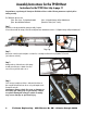
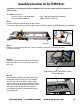
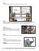
Step 5
Lay one track section on a flat floor with the “front” side up. This is
determined by the space between the track cross bar and the track
section edge as shown above.
Step 6
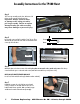
Attach splice plates to the bottom section of the track. Splice plates are mounted on the outside track section. Slide the top
section track into the groves on the inside track section, attach with 2 nuts and bolts per side (Pictures 4 & 5).
NOTE: DO NOT SUBSTITUTE NUTS AND BOLTS
Use 3/8”x 3/4” bolts and 3/8” nut keeps (lockwasher and nut combined).
Front
Back
Picture 5
Picture 4
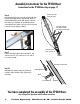
Step 7
Reattach the top cap to the end of the last section of track
section you intend to use. Assemble with two 3/8”x 3/4” hex
head bolts with lock nuts provided. Make sure that the top cap
end slides into the outside of the track section (shown right).
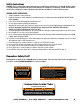
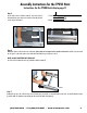
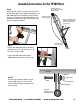
Assembly Instructions for the TP400 Hoist
Step 4
“Roll”carriage assembly onto the base. At this time lock
the base in place using the Safety Pin as shown.
Important: Always check for wear
or damage to the safety pin cable/
pull ring assembly. Failure to replace
damaged safety pin cable assembly
may cause damage or personal injury.