INSTALLATION INSTRUCTIONS For HUD Code Wind Zone 1, or IBC 2009, 90 mph, Exposure C Version 12/9/2009 INDEX Approval PAGE SECTION NUMBER INTRODUCTION 2 GENERAL INSTALLATION 3 PARTS LIST 4&5 LONGITUDINAL DEVICES 6 PIER HEIGHTS 7 Roof Pitch 8 SET-UP INSTRUCTIONS 9 FOOTER SIZES WIND ZONE I - SINGLE 10 - DOUBLE 11 - TRIPLE 12 - HIGH PIER 13 V-DRIVE & PIER SYSTEMS 14 SOIL CLASSIFICATION 15 CONCRETE INSTALLATION 16 & 17 ASPHALT INSTALLATION 18 D1095 COMPONENT PAR
TIE DOWN ENGINEERING VECTOR DYNAMICS INSTALLATION DESIGN INSTRUCTIONS Introduction These instructions describe the proper use of the lateral and longitudinal foundation system. You may also refer to the home manufacturer’s installation manuals that include the Vector Dynamics system as an alternate foundation system.
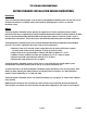
GENERAL INSTALLATION INSTRUCTIONS SITE PREPARATION It is necessary that the home site be properly graded and sloped to prevent water and moisture from standing or flowing beneath the home. FOOTINGS AND FROST LINES The Vector Dynamics Foundation System was designed to be placed directly on top of the ground (or poured concrete) after clearing all loose vegetation. In areas with frost heave, use Vector for Poured Concrete (see pages 16 & 17) to comply with local requirements for footer depth.
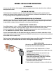
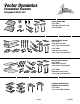
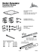
Vector Dynamics Foundation Systems Component Parts List Vector System 2000 Part # 59018 Single piece pads with straps and slotted bolts Concrete Vector System Part # 59036 Single piece pads with swivel straps and slotted bolts Part # 59008 Single piece pads without swivel straps and slotted bolts Concrete Vector System Part # 59049 Double block pads with swivel straps and slotted bolts Part # 59006 Double block pads without swivel straps and slotted bolts Longitudinal Stabilization Hardware Kit for Conc
Vector Dynamics Foundation Systems Component Parts List Vector 2000 3 Sq. Ft.
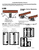
Longitudinal Stabilizer Devices As an alternate to installing longitudinal anchors and stabilizer plates, the installer may use longitudinal stabilizing devices, including Tie Down's LSD (Longitudinal Stabilization Device). The use of LSD systems on a single or multi section home replaces longitudinal anchors, stabilizer plates and straps. LSD Combine Vector Dynamics & LSD 2 3 4 1 1. Longitudinal Foundation Pad 2. Beam Clamp (2 per system) 3. Longitudinal Strut (2 per system) 4.
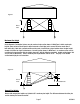
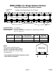
Figure 1 50 in. max. Maximum Pier Height Vector Dynamics Foundation Systems may be used on single section homes in Wind Zone I which require pier heights (from surface of Vector pads to top of concrete or metal pier) not to exceed 50 inches under one or both main rail(s). Note that a ground anchor must be used at each Vector system location where the pier height exceeds 24 inches for single section homes.
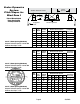
Federal Manufactured Home Construction & Safety Standards Pier Height Max. Unit Length for Number of Vector Systems 2 3 4 5 6 136 32" 96" 28' 41' 55' 69' 80' 1 142 36" 96" 28' 42' 56' 70' 80' 1 156 44" 96" 28' 43' 58' 72' 80' 1 164 56" 96" 27' 40' 54' 68' 80' 1 176 56" 96" 28' 42' 56' 70' 80' 1 180 56" 96" 28' 42' 56' 70' 80' 1 186 56" 96" 28' 42' 56' 70' 80' 2 Max. Pier Height Max. Sidewall Height Max. Sidewall Height Max.
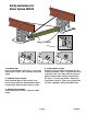
Set-Up Instructions for Vector System #59018 Long U-Bolts A B C 1. Set Vector Pads Clear all vegetation where pads will rest. Place a long U-bolt in pad as shown. Press or hammer pad into the ground. 2. Set Block or piers on pads. Center foundation blocks or piers on pads. Place pre-cut center compression member between blocks, resting on pads, centers between U-bolts as shown. D 4. Inside brackets & straps Attach the inside tie brackets to the U-bolts over the compression member.
WIND ZONE I for Single Section Homes Using Vector Dynamics Foundation Systems Longitudinal (LSD) Example of a Single Section 14' x 72' Home Vector Systems Anchors & Stabilizers Longitudinal (LSD) Soil Classifications: 2, 3, 4A & 4B Soil Bearing Capacity: 1,000 PSF Minimum Anchors Required: 30" with 2-4" helix anchors (#59095) & 12" Stabilizer Plates (#59292) with 1-1/4" Frame Ties Home Length Vector Systems Anchors Required Required Per Side Up To 24" Pier 24+" Piers Longitudinal Systems* (LSD) 0
WIND ZONE I for Double Section Homes Using Vector Dynamics Foundation Systems Example of a Double Section 28' x 72' Home Vector System Longitudinal (LSD) Longitudinal (LSD) Vector System Vector Systems Soil Classifications: 2, 3, 4A & 4B Soil Bearing Capacity: 1,000 PSF Minimum Anchors Required*: None (*Marriage wall and sheer wall anchors may be required by home manufacturer.
WIND ZONE I for Triple Section Homes Using Vector Dynamics Foundation Systems LSD Example of a Triple Section 32' x 72' Home LSD Vector Systems LSD LSD Tag or Full Triple Soil Classifications: 2, 3, 4A & 4B Soil Bearing Capacity: 1,000 PSF Minimum Anchors Required*: None (*Marriage wall and sheer wall anchors may be required by home manufacturer.
WIND ZONE I for Double Section Homes (High Pier Sets) Using Vector Dynamics Foundation Systems Example of a Double Section 28' x 72' Home LSD Vector System LSD Vector System Anchors & Stabilizer Plates Soil Bearing Capacity: 1,000 PSF Minimum Anchors Required: 30" with 2-4" helix anchors (#59095), 12" Stabilizer Plates (#59292) & 1-1/4" frame tie with connector Home Length Vector Systems Required Anchors Required Per Side Longitudinal System (LSD)* 0 to 48' 2 2 2 (4 Struts) 49' to 71' 3 3
Vector Dynamics Metal Pier & V-Drive Installation METAL PIER FOUNDATIONS For metal piers, place the piers in the center of the Vector pads. Set the single 4x4 or two 2x4’s through the piers, and bumps against the outside tension brackets. Inside tie brackets mount “upside down” as shown in drawing. Metal piers using the Vector System can only be used on level ground sets. Conventional pier adjusters must be placed under beam with upturned edge directed towards the outside of the home.
VECTOR DYNAMICS INSTALLATION DESIGN INSTRUCTIONS Vector Dynamic Foundation Systems may be used only on homes set on soils classified as Class 2, 3, 4A and 4B as described in the table below: SOIL CLASSIFICATIONS Soil Class Types of Soils 1 Sound hard rock...... Blow Count (ASTM D2586) NA Soil Test Probe (1) Torque Value (2) NA Very dense and/or cemented sands, coarse gravel and cobbles, preloaded silts, clays, and coral’s 40-up More than 550 lbs - in. 2 24-39 350-549 lbs - in.
Vector Dynamics System for Concrete Applications Instructions These instructions are an addendum to the standard Vector Dynamics instructions. Read and follow all applicable instructions and guidelines in the Vector instructions and home installation manual. The Vector system for concrete pads applies to concrete footers, runners and slabs. Minimum size of concrete per Vector pier is 24” x 24” x 4” or 18” round (min) x 10” deep.
Vector Dynamics System for Concrete Applications Instructions 9. 10. 11. 12. 13. 14. 15. 16. 17. Put a washer and nut on one of the 3/8” x 3-3/4” wedge anchors. The nut should be screwed on enough to have 1 or 2 threads showing on the top of the bolt. Place the wedge end of the bolt into one of the holes, going through the outside tension bracket, metal Vector pad and into the concrete. Using a hammer, tap the wedge bolt into the hole. Maximum height for expansion bolt above concrete is 2”.
Asphalt Installation These Asphalt instructions are an addendum to the standard Vector Dynamics concrete instructions. Read and follow all applicable guidelines in the instructions for Vector, the home, office, classroom or portable building being installed. Minimum depth of asphalt is 2 inches with a suitable base material compacted under the asphalt. This system is designed for portable classrooms, offices or other structures using I-beam frames.
TIE DOWN ENGINEERING • 255 Villanova Drive SW • Atlanta, GA 30336 www.tiedown.