Owners Manual WH-HD-IRN-MG-948 WH-HD-IRN-MG-1054 Water Softener Plus Iron and Manganese Reduction 1. Read all instructions carefully before operation. 2. Avoid pinched o-rings during installation by applying NSF certified lubricant to all seals (provided with install kit). 3. This system is not intended for treating water that is microbiologically unsafe or of unknown quality without adequate disinfection before or after the system.
Table of Contents 2 READ THIS PAGE FIRST BEFORE STARTING INSTALLATION 3 EFFICIENCY STATEMENT 4 HOW YOUR WATER CONDITIONER WORKS 4 SPECIFICATIONS SPECIFICATION / SYSTEM DIMENSIONS 5 INSTALLATION UNPACKING / INSPECTION OF TWIN TANK MODEL BEFORE INSTALLATION PREPARATIONS / INSTALLATION STEPS INSTALLING BRINE TANK WATER SOFTENER INSTALLATION 6 7 8 9 10 OPERATION STARTUP INSTRUCTIONS MANUAL REGENERATION 11 12 MAINTENANCE INSTRUCTIONS 13 RES-UP® FEEDER INSTALLATION INSTRUCTIONS 14 MASTER PROGR
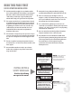
READ THIS PAGE FIRST BEFORE STARTING INSTALLATION Read this manual thoroughly to become familiar with the device and its capabilities before installing or operating your Water Filter. Failure to follow instructions in this manual could result in personal injury or property damage. This manual will also help you to get the most out of your filter. This system is intended for use on municipal water only and its installation must comply with all State, provincial or local regulations.
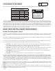
EFFICIENCY STATEMENT IAPMO R & T Certified against CSA B483.1 This product is efficiency rated according to NSF/ANSI 44. The stated efficiencies are valid only at the specified salt dosages and maximum service flow rate. PERFORMANCE DATA SHEET MODEL NUMBER Oty High Capacity Resin WH-HD-IRN-MG-948 WH-HD-IRN-MG-1054 1.0 113 1.5 ftl Rated Service Flow (gpml 11.0 11.2 Pressure Drop at Rated Service Flow (ps1J 15.0 15.0 Rated Softening Capacity lgrainsJ 13,629 Kl 3lbs 20,4A3 Kl 4.
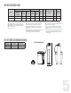
SPECIFICATION Capacity Grains Flow Rate Mineral Salt Shipping Resin Brine Tank Size @ 15 lbs/cu ft Cap Weight @10 lbs/ @6 lbs/ Service Backwash Tank Cu. Ft. Inches Factory Lbs Lbs cu ft) cu ft USGPM USGPM Size Setting Model WH-HD-IRN-MG-948 30, 000 26,500 22,000 10.0 2.0 9 x 48 1.00 18.1 X 34. 7 270 1 20 WH-HD-IRN-MG-1054 45, 000 39,750 33,000 12.0 2.4 10 x 54 1.50 18.1 X 34.
UNPACKING / INSPECTION OF TWIN TANK MODEL Be sure to check the entire unit for any shipping damage or parts loss. Also note damage to the shipping cartons. Contact the transportation company for all damage and loss claims. The manufacturer is not responsible for damages in transit. Small parts, needed to install the Softener, are in a parts box. To avoid loss of the small parts, keep them in the parts bag until you are ready to use them. What is included in the box? 1. Control Valve 1. Control Valve 2.
BEFORE INSTALLATION Make sure you have a copy of your most recent water test results. If your water has not been tested previously you can contact your supplier of this product to obtain a water sample bottle to be sent to one of our facilities for a free analysis. It is important that this product not be installed until you have this information.
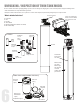
PREPARATIONS Clips Attaching Bypass to Valve (If required in case of replacing the control valve. The new control valve comes with bypass attached) Make sure the bypass is attached well to the control valve. Connect the straight or elbow connectors to the bypass with red clips. Connect the inlet and outlet of the water Softener to the plumbing of the house. The control valve must not be submitted to temperatures above 43°C (110°F).
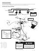
INSTALLING BRINE TANK a) Attach the three brine grid legs to grid plate. The legs will snap on to the tabs of the salt plate making a “click” sound. For square brine tank there are four legs.) c) Drop the brine grid with brine well inside the brine tank such that the nut fitting faces the hole on the brine tank. Then press the grid evenly inside the brine tank until the brine grid legs touches the bottom of the brine tank.
INSTALLATION Connect Softener to the HousePlumbing Any solder joints near the valve must be done before connecting any piping to the valve. Always leave at least 6” (152 mm) between the valve and joints when soldering pipes that are connected to the valve. Failure to do this could cause damage to the valve.
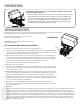
STARTUP INSTRUCTIONS Familiarize with Button Configuration: 1. Connect the transformer 1 to the valve. Plug the 12-volt transformer into a 120 VAC 60 Hz outlet. 2. Open the brine tank / cabinet salt lid and add water until there is approximately 3” (75 mm) of water in the tank. Do not add salt to the brine tank at this time. Key Pad Configuration: This function is to enter the basic set up information required at the time of installation.
Manual Regeneration To start an immediate regeneration turn the knob clockwise from the service position (9:00) to the 10:00 position. Within a few seconds the an immediate regeneration will begin. Using the knob you can manually advance to the next position. Pressing any button will also advance to the next position. For Delayed Regeneration, Press Settings Button Once BA.WA. BACKWASH SERV.
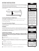
MAINTENANCE INSTRUCTIONS AND SCHEDULE System Check List NOTE** All units are factory programmed for the correct size and regeneration cycle alteration should only be done by a factory trained technician or after consultation with one of our technical representatives if you have any questions please call: 1-855-378-9116 4a. Open the inlet on the bypass valve slightly and very slowly allow water to enter the unit.
Care of Your Softener To retain the attractive appearance of your new water softener, clean occasionally with a mild soap solution. Do not use abrasive cleaners, ammonia or solvents. Never subject your softener to freezing or to temperatures above 43°C (110°F). Servicing Components The injector assembly should be cleaned or replaced every year depending on the inlet water quality and water usage.
Res-Up® Feeder Installation Instructions Round Brine Tank - continued 4. IInstall the holder and the Res Care Solution 5. Take off the small hole cover on the Brine Well lid. 6. Take off the cover of the Res care bottle . Insert the wick, making sure it touches the bottom of the bottle. Insert the other end of the tube completely into the hole in the brine well cap. Automatic feeding will start in a few hours. Install Resup Feeder -Square Brine Tank 1.
Install Resup Feeder -Square Brine Tank - continued 4. IInstall the holder and the Res Care Solution 5. Take off the small hole cover on the Brine Well lid. 6. Take off the cover of the Res care bottle . Insert the wick, making sure it touches the bottom of the bottle. Insert the other end of the tube completely into the hole in the brine well cap. Automatic feeding will start in a few hours.
MASTER PROGRAMMING Familiarize with Button Configuration: Key Pad Configuration: This function is to enter the basic set up information required at the time of installation. This function is to accept the values if changed and advance to the next page in the menu. These buttons are used to increase or decrease the value of the settings while in the programming mode. PROGRAMMING LEVELS There are 3 levels to the valve program. Master options and Factory options are typically adjusted at the factory.
MASTER PROGRAMMING MASTER OPTIONS (LEVEL III) Press SET key UP or DOWN key Press UP or DOWN key Press SET key to advance each page. to change value. to accept value. Press UP or DOWN key to advance to next page. VALVE TYPE The valve must be designated as either SOFTENER or FILTER. This change will determine what options are available in the Factory Settings. METER RATIO The meter ratio calibrates the pulse from the flow meter into gallons. This value is factory set and should not be changed.
MASTER PROGRAMMING FACTORY OPTIONS (LEVEL II) Press UP or DOWN key Hold until you hear a beep (3 seconds). Press UP or DOWN key to change value. Press SET key accept change and advance to next page. SOFTENER MODE CALENDAR CLOCK METER IMMEDIATE METER DELAYED METER OVERRIDE REG. TIME 02:00 AM CAPACITY 27500 REG. TIME 02:00 AM REG.
MASTER PROGRAMMING USER SETTINGS (LEVEL I) Press SET key Press UP or DOWN key to change value. Press SELECT to accept change and advance to next page. SOFTENER MODE CALENDAR CLOCK METER IMMEDIATE METER DELAYED METER OVERIDE TIME 10:15 AM TIME 10:15 AM PEOPLE 04 PEOPLE 04 REG. DYS 03 HARDNESS 020 GPG HARDNESS 020 GPG HARDNESS 020 GPG PEOPLE 04 PEOPLE 04 PEOPLE 04 REG. DYS 03 CAUTION: The values in this page are for illustration purpose and can be changed by the factory without notice.
Toll-Free: 1-855-378-9116 80150302 12/18