
Instructions / Assembly


14
Optional
Overow
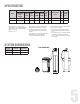
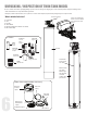
Assembly
Brine Valve
Connector Detail
A
C120V/10A
C
urrent Protect Socket
Brine Elbow
Assembly
Water Pipe Outlet
Main tank
5/8” Drain Line
Bypass assembly
5/8” Overow Line
Floor drain
Optional
Pipes Fixed
Structure
Drain Elbow
Assembly
Outlet
Brine Tank
3/8” Brine Tube
Inlet
Water Pipe Inlet
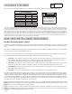
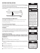
Downflow Water Softener Installation
*NOTE
Check local plumbing codes
in regards to requirements
for use of Check Valve or
back flow prevention or
vacuum breaker
Cold (Raw water)
Cold (Filtered water)
Cold (Raw water)
Check Valve
Water Heater
Hot (Soft Water)
Downow Water Softener
Filter
InIn Out
Out
Cold (Soft Water)
T
o Outside Faucet
InOut
*
Outlet
Inlet
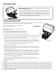
NOTICE - THERE ARE RAISED
ARROWS ON THE BYPASS
ASSEMBLY INDICATING
DIRECTION OF WATER FLOW
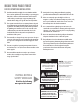
Connect Softener to the HousePlumbing Any solder joints near the valve must be done before connecting any piping to the valve. Always leave at least 6” (152 mm)
between the valve and joints when soldering pipes that are connected to the valve. Failure to do this could cause damage to the valve.
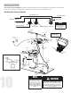
CAUTION!
Never insert drain line
10
directly into a drain, sewer line, or trap.
Always allow an air gap between the drain
line and the wastewater to prevent the
possibility of sewage being back-siphoned
into the conditioner.
NOTE
Waste connections or drain
outlet shall be designed and
constructed to provide for
connection to the sanitary
waste system through an
air-gap of 2 pipe diameters
or 1 inch (22 mm) whichever
is larger.
INSTALLATION