
Instructions / Assembly


12
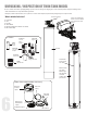
Downflow Valve
Inlet
Outlet
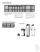
Attaching Bypass to Valve (If required in case of replacing the control valve. The new control
valve comes with bypass attached)
Make sure the bypass is attached well to the control valve. Connect the straight or elbow connectors to
the bypass with red clips. Connect the inlet and outlet of the water Softener to the plumbing of the
house. The control valve must not be submitted to temperatures above 43°C (110°F). When sweat
fittings are used, to avoid damaging the control valve, solder the threaded copper adapters to the
copper pipe and then, using Teflon tape, screw the assembly into the bypass valve.Do not use pipe
thread compound as it may attack the material in the valve body.
PREPARATIONS
Clips
Bypass
2. Water Lines
8
Determine the best location for your water Softener, bearing in mind the location of your water supply lines, drain line and 120 volt AC electrical
outlet. Subjecting the Softener to freezing or temperatures above 43°C (110°F) will void the warranty.
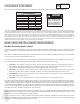
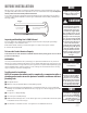
INSTALLATION STEPS
Please notice the inlet and outlet labels on the valve as shown here to
determine the position of the equipment:
For DF Softener - The inlet should be on the left hand side of the valve
and out on the right hand side
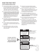
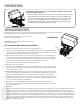
Facts to Remember When Planning Your Installation
1. All installation procedures must conform to local and state or provincial plumbing codes.
2. Outside faucets used to water lawns and gardens should not supply untreated water, replace untreated water with feed water
to the unit. If necessary to do this please install check valve, see page 14. A new water line is often required to be connected to
supply untreated water to the inlet of the water lter and to the outside faucets.
3. Make sure the bypass is attached well to the control valve. Connect the straight or elbow connectors to the bypass with red
clips. Connect the inlet and outlet of the water lter to the plumbing of the house. The control valve must not be submitted
to temperatures above 43°C (110°F). When sweat ttings are used, to avoid damaging the control valve, solder the threaded
copper adapters to the copper pipe and then, using Teon tape, screw the assembly into the bypass valve.
Do not use pipe thread compound as it may attack the material in the valve body.
4. Apply Teon Tape and Orings to the ttings
5. Connect Filter to the house plumbing. Any solder joints near the valve must be done before connecting any piping to the valve.
Always leave at least 6” (152 mm) between the valve and joints when soldering pipes that are connected to the valve. Failure to
do this could cause damage to the valve.
6. Drain Line connection: Using Teon tape, screw the 1/2” hose barb and attach oring into the drain port in the valve. Attach
1/2” drain hose (Supplied with some models and brands) to the hose barb and tighten securely with a hose clamp (Supplied
with some models and brands). Run the drain line to a oor drain or a laundry drain. Complete any necessary plumbing.
7. Using the Allen Key (included), place the unit in the bypass position. Slowly turn on the main water supply. At the nearest cold
treated water tap nearby remove the faucet screen, open the faucet and let water run a few minutes or until the system is free
of any air or foreign material resulting from the plumbing work.
8. Make sure there are no leaks in the plumbing system before proceeding. Close the water tap when water runs clean.
9. Open the brine tank / cabinet salt lid and add water until there is approximately 3” (75 mm) of water in the tank. Do not add
salt to the brine tank at this time.
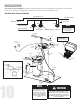
Outside faucets used to water lawns and gardens should not supply softened water. A new water line is often required to be connected to supply hard water to the inlet of
the water softener and to the outside faucets. Cut the water line between where it enters the house and before any lines that branch o to feed the hot water heater or
other xtures in the house and as near the desired location of the water softener as possible. Install a tee tting on the feed end of the cut pipe, and an elbow tting on the
other end. Install piping from the tee to the inlet of the water softener and from the elbow to the outlet of the softener. To sever the water lines which branch o to feed any
outside faucets, cut the branch lines approximately two inches from the tting on the main water line. Install an elbow on the end of the pipe nearest the outside faucet and
a cap on the end connected to the existing water line. Install piping from the tee installed on the inlet line to the water softener to the elbow installed on the pipe to the
outside faucet. Following this procedure will result in all lines in the house, with the exception of the outside faucets, but including the water heater and therefore the hot
water lines, being supplied with soft water.