TM Refrigerant Recovery Machine RG6000 1 Operating Manual Manuel d’utilisation Bedienungsanleitung Manual de operaciones
Safety Precautions WARNING : To prevent personal injury and / or equipment damage, ALLOW ONLY QUALIFIED PERSONNEL TO OPERATE THIS UNIT. Before operating the unit, read and follow the instructions and warnings in this manual. The operator must be familiar with air conditioning and refrigeration systems, refrigerants, and the dangers of pressurized components. If the operator cannot read this manual, operating instructions and safety precautions must be read and discussed in the operator’s native language.
Table of Contents Understanding Refrigerant Recovery . . . . . . . . . . . . . . . . . . . . . . . . 4 Standard Operating Instructions . . . . . . . . . . . . . . . . . . . . . . . . . . . 5 Setup . . . . . . . . . . . . . . . . . . . . . . . . . . . . . . . . . . . . . 5 Recovery Procedure . . . . . . . . . . . . . . . . . . . . . . . . . . . . . 6 Purge the RG6000 Unit . . . . . . . . . . . . . . .
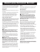
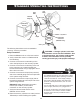
Understanding Refrigerant Recovery Hoses Refrigerant recovery is the processs of taking refrigerant out of a system and storing it in a cylinder. The following information is critical to achieving the best refrigerant recovery results. Hoses must be equipped with low-loss fittings and have pressure ratings appropriate for the refrigerant in the system being serviced. Refrigerant Shut-off Switch Identify the refrigerant type and quantity in the system to be serviced.
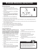
Standard Operating Instructions Inlet Fitting Sight Glass Manifold Gauge Set Filter / Drier System Being Serviced Outlet Fitting Liquid Port Liquid Recovery Cylinder Vapor Float Switch Connection (RG6000-KT only) Scale The following instructions are for a standard or “common” recovery procedure. warning : A storage cylinder is full when it reaches 80% volume. DO NOT OVERFILL.
Standard Operating Instructions Recovery Procedure 1. Connect the unit to a 115V outlet. 2. Slowly open the liquid valve of the recovery cylinder while watching hoses and connections for leaks. 3. Set the recover / purge valve on the RG6000 unit to RECOVER. 4. Open the liquid valve on the manifold gauge set. Note: Opening the liquid valve removes liquid from the system first, greatly reducing recovery time. 5. Open the outlet valve on the RG6000 unit. 6. Toggle the power switch to the ON position. 7.
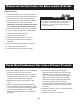
Operating Instructions for Bulk Liquid Systems “Push – Pull” Procedure The push – pull method removes bulk liquid from a system using the pressure differential created by the recovery machine. This method works only with large systems where the liquid is readily accessible; it may not work on systems that contain less than 15 lbs. bulk liquid. Liquid Recovery This method is used : • on systems with receiver cylinders. • on systems containing more than 20 lbs. of refrigerant.
Operating Instructions for Bulk Liquid Systems Vapor Recovery 1. Place the RG6000 unit on a flat, level surface. 2. Connect a hose from the inlet side of the unit to the liquid port of the system being serviced. Tech Tip 3. Connect a hose from the outlet side of the unit to the liquid port on a recovery cylinder. For a faster recovery procedure, recover from both the liquid and vapor ports of the system being serviced by using a tee fitting or manifold gauge set in the hose setup.
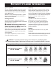
Recovery Cylinder Information Type of Cylinder Capacity Use only authorized, refillable, refrigerant storage cylinders. Federal regulations require refrigerant to be transported only in containers meeting DOT specs. 4BW or 4BA. Safety codes state that closed cylinders should not be filled with liquid over 80% of volume. (The remaining 20% is called head pressure room.) Do not exceed 80% of cylinder capacity. PROMAX recommends the use of the TIF9010A Refrigerant Scale for monitoring cylinder capacity.
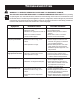
Troubleshooting WARNING: To prevent personal injury and / or equipment damage, ALLOW ONLY QUALIFIED PERSONNEL TO OPERATE AND REPAIR THIS UNIT. Before operating or repairing the unit, read and follow the instructions and warnings in this manual. The technician must be familiar with air conditioning and refrigeration systems, refrigerants, and the dangers of pressurized components.
Replacement Parts 1 (left side shown) Motor Relay & Capacitor Divider 2 3 4 16 15 17 18 } 14 Motor Interface 6 5 Counterbalance 7 13 11 12 Inlet / Outlet Tubes 10 8 9 Item Part No. No. Qty. Description 1 2 3 4 550495 550496 550503 SK-6013 SK-6005 1 1 1 1 1 5 SK-6017 1 6 Sk-6008 1 7 8 9 10 11 GA1000 100124 100123 100122 SK-6014 1 1 1 1 1 19 RG6000-KT only Item Part No. No. Qty. Description Case Half (left) Case Half (right) Grommet (1 ea.
Rebuild Kits and Accessories Part No.
Maintenance CAUTION : To prevent personal injury, disconnect the RG6000 from the power supply before performing maintenance. Installation of the Filter and Filter / Drier 1. Before performing a refrigerant recovery, always inspect and clean the filter screen in the inlet fitting on the RG6000 unit. Replace the filter screen (p/n SK-6001) if necessary. A filter screen greatly reduces the risk of damage to the unit by preventing foreign material from entering the unit and the system being serviced.
Full One-Year Limited Warranty Einjährige Garantie Unit Serial No. Serien-Nr. des Geräts This product is warranted to be free from defects in workmanship, materials and components for a period of one year from date of purchase. Es wird garantiert, dass dieses Produkt während des Zeitraums von einem Jahr ab Kaufdatum frei von Material-, Komponenten- und Verarbeitungsfehlern ist. The following restrictions apply: Es gelten folgende Beschränkungen: 1. This warranty is non-transferable.
Owatonna, MN 55060 Phone : 800.327.5060 Fax: 866.287.7222 www.PromaxRecovery.com © 2008 SPX Form No. 551691 Rev. B, 27 January 2010 Designed & Engineered in the USA Manufactured in China Entworfen und entwickelt in den USA Hergestellt in China Conçu et mis au point aux États-Unis Fabriqué en Chine Diseñado en EE.UU.