BENGAL BRUTE ASSEMBLIES Current as of 06/09/2010 CNH T6010-80 MAXXUM 110,115,120, 125,130,140,155 PARTS LISTING WITH MOUNTING AND OPERATING INSTRUCTIONS Tiger Corporation 3301 N. Louise Ave. Sioux Falls, SD 57107 1-800-843-6849 1-605-336-7900 www.tiger-mowers.
TO THE OWNER / OPERATOR / DEALER All implements with moving parts are potentially hazardous. There is no substitute for a cautious, safe-minded operator who recognizes the potential hazards and follows reasonable safety practices. The manufacturer has designed this implement to be used with all its safety equipment properly attached to minimize the chance of accidents. BEFORE YOU START!! Read the safety messages on the implement and shown in this manual.
FORWARD This manual contains information about many features of the Tiger mowing and roadside maintenance equipment. Some of these include: Safety precautions, Assembly instructions, Operations, Maintenance and Parts. This manual will also assist you in the proper break-in, daily care, and troubleshooting of your new mower. We recommend that you read carefully the entire manual before operating the unit.
TABLE OF CONTENTS SAFETY_____________________________________________ 1-1 Safety Information__________________________________ 1-2 ASSEMBLY / MOUNTING SECTION_______________________ 2-1 OPERATION SECTION_________________________________ 3-1 MAINTENANCE SECTION______________________________ 4-1 PARTS SECTION_____________________________________ 5-1 Parts Ordering Guide_______________________________ 5-2 Parts Table of Contents______________________________ 5-3 Common Parts Section___________________________
SAFETY SECTION Safety Section 1-1
SAFETY A safe and careful operator is the best operator. Safety is of primary importance to the manufacturer and should be to the owner / operator. Most accidents can be avoided by being aware of your equipment, your surroundings, and observing certain precautions. The first section of this manual includes a list of Safety Messages that, if followed, will help protect the operator and bystanders from injury or death.
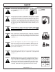
SAFETY Si no lee Ingles, pida ayuda a alguien que si lo lea para que le traduzca las medidas de seguridad. (SG-3) DANGER! Never operate the Tractor or Implement until you have read and completely understand this Manual, the Tractor Operator’s Manual, and each of the Safety Messages found in the Manual or on the Tractor and Implement. Learn how to stop the tractor engine suddenly in an emergency. Never allow inexperienced or untrained personnel to operate the Tractor and Implement without supervision.
SAFETY DANGER! Never allow children or other persons to ride on the Tractor or Implement. Falling off can result in serious injury or death. (SG-10) DANGER! Never allow children to operate or ride on the Tractor or Implement. (SG-11) WARNING! Do not mount the Tractor while the tractor is moving. Mount the Tractor only when the Tractor and all moving parts are completely stopped. (SG12) DANGER! Start tractor only when properly seated in the Tractor seat.
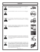
SAFETY WARNING! The operator and all support personnel should wear hard hats, safety shoes, safety glasses, and proper hearing protection at all times for protection from injury including injury from items thrown by the equipment. (SG-16) CAUTION! PROLONGED EXPOSURE TO LOUD NOISE MAY CAUSE PERMANENT HEARING LOSS! Tractors with or without an Implement attached can often be noisy enough to cause permanent hearing loss.
SAFETY WARNING! Never attempt to lubricate, adjust, or remove material from the Implement while it is in motion or while tractor engine is running. Make sure the tractor engine is off before working on the Implement. (SG-20) WARNING! Periodically inspect all moving parts for wear and replace when necessary with authorized service parts. Look for loose fasteners, worn or broken parts, and leaky or loose fittings. Make sure all pins are properly secured.
SAFETY DANGER! NEVER use drugs or alcohol immediately before or while operating the Tractor and Implement. Drugs and alcohol will affect an operator’s alertness and coordination and therefore affect the operator’s ability to operate the equipment safely. Before operating the Tractor or Implement, an operator on prescription or over-the-counter medication must consult a medical professional regarding any side effects of the medication that would hinder their ability to operate the Equipment safely.
SAFETY DANGER! WARNING! WARNING! WARNING! WARNING! The rotating parts of this machine have been designed and tested for rugged use. However, the blades could fail upon impact with heavy, solid objects such as metal guard rails and concrete structures. Such impact could cause the broken objects to be thrown outward at very high velocities. To reduce the possibility of property damage, serious injury, or even death, never allow the cutting blades to contact such obstacles.
SAFETY WARNING! Do not mow with two machines in the same area except with Cab tractors with the windows closed. (SGM-11) DANGER! Rotary and Flail Mowers are capable under adverse conditions of (100 yards or more) and throwing objects for great distances causing serious injury or death. Follow safety messages carefully.
SAFETY Relieve hydraulic pressure prior to doing any maintenance or repair work on the Implement. Place the Mower Head on the ground or securely supported on blocks or stands, disengage the PTO, and turn off the engine. Push and pull the control Levers or Joystick several times to relieve pressure prior to starting any maintenance or repair work. (SBM-6) DANGER! Always keep a careful lookout and use extreme care when working around overhead obstructions.
SAFETY WARNING! Engine Exhaust, some of its constituents, and certain components contain or emit chemicals known to the state of California to cause cancer and birth or other reproductive harm. WARNING! Battery posts, terminals and related accessories contain lead and lead compounds, chemicals known to the state of California to cause cancer and birth or other reproductive harm.
SAFETY PART NO.
SAFETY PART NO.
SAFETY PART NO.
SAFETY PART NO. LOCATION 22840 INSIDE OF CAB 24028 MOWER DECK 25387 INSIDE OF CAB 10” x 5.5” 31522 MOWER DECK, MAIN BOOM 18.25” x 10” 31523 HYDRAULIC TANK 13.
SAFETY PART NO.
SAFETY PART NO.
SAFETY PART NO.
SAFETY PART NO.
SAFETY PART NO.
SAFETY PART NO.
SAFETY PART NO.
SAFETY TB1011 MOWER DECK 34852 HYDRAULIC TANK Safety Section 1-23
SAFETY ITEM PART NO. QTY. DESCRIPTION 1 50023 00776031 33997 AVAIL 1 1 * * * AVAIL 1 1 1 4 MANUAL CANISTER COMPLETE ROUND MANUAL CANISTER DECAL, SHEET, MANUAL CANISTER DECAL DECAL DECAL SPECIFIC PRODUCT MANUAL E M I SAFETY MANUAL FRONT ADHESIVE PAD REAR ADHESIVE PAD ZIP TIE 14” LONG 2 3 4 5 6 7 8 9 * 33753 34296 34297 6T1823 NOTE: The manual canister can be bolted, zip tied or adhered to a variety of surfaces. Locate a protected area within the view of the operator.
SAFETY FEDERAL LAWS AND REGULATIONS This section is intended to explain in broad terms the concept and effect of federal laws and regulations concerning employer and employee equipment operators. This section is not intended as a legal interpretation of the law and should not be considered as such. Employer-Employee Operator Regulations U.S. Public Law 91-596 (The Williams-Steiger Occupational and Health Act of 1970) OSHA This Act Seeks: “...
SAFETY Safety Section 1-26
ASSEMBLY SECTION Assembly Section 2-1
ASSEMBLY Before attempting to mount or service your Tiger mower, it is important to read and understand all of the information in the Safety section of this manual. Check complete shipment list against the packing list to make sure there are no shortages. Make certain the tractor model is the appropriate one for the mower received! Use a floor jack, hoist or fork lift to lift or raise heavy parts whenever possible whether mentioned or not.
ASSEMBLY CRANKSHAFT ADAPTER If necessary remove the four cap-screws from the crankshaft pulley. Then install the crankshaft adapter and spacer to the pulley with cap-screws and lock-washers as shown in the parts section. FRONT PUMP MOUNTING Install the pump mounting bracket on the front of the tractor with cap-screws and lock-washers as shown in the parts section illustration. DO NOT tighten fasteners at this time. Slide the pump drive shaft into the crankshaft adapter.
ASSEMBLY WEATHER-PACK/METRI-PACK ASSEMBLY These instructions apply to both Weather-Pack and Metri-pack connectors. NOTE: Use the specific tool for the type of connector you are assembling. 1. Apply seal to cable, before stripping insulation. 2. Align seal with cable insulation. 3. Put terminal in crimping tool, then position wire and seal in place. 4. Crimp and visually inspect for a good crimp before installing in connector body.
ASSEMBLY POLY-CARBONATE SAFETY WINDOW NOTE: This should be done before mounting the main frame. 1. Disconnect gas shock at door. Remove the right side cab door from tractor cab by removing hinge pins. 2. Remove the existing hardware and discard factory glass door. 3. Place small bead of adhesive seal in the bottom of the trim lock bubble bead. 4. Install trim lock bubble seal on polycarbonate starting at the center bottom horizontal portion. 5.
ASSEMBLY LIFT VALVE MOUNT Drill a Ø9/16” hole in the fender frame tube of the tractor 3/4” back of the existing hole (away from cab). Install the right valve mounting bracket to the inside of the right fender frame tube as shown below and attach it with hardware listed in the parts section of this manual. Repeat these steps for the left valve mounting bracket. Align the valve mounting plate with the drilled holes.
ASSEMBLY HOSE AND CABLE ROUTING Attach two clamps to the right rear wheel well for proper hose/cable routing. Drill one hole for each clamp. Use the lower rear corner of the wheel well as an origin for measuring. The holes should be 10mm or 3/8” reamed to accept 3/8” hardware. Measure from the back edge of the wheel well 13-1/2” from the origin. Use a square to measure 3-1/2” up. Refer to the image below to see the first hole. The second hole should run parallel to the bottom edge of the wheel well.
ASSEMBLY CABLE CONTROL LEVER STAND Place the front edge of the support bracket 2 ¾” back from the lower right front window. Rotate stand to be 2 ¼” from the right door frame as shown below. Be sure that the location of the stand will allow clearance between the cable control handles and all existing interior levers, etc. Drill 3 holes to match control bracket and secure with cap-screws and nylock nuts noted in parts section. Cut a 2 ¼” hole in the floor from inside the cab.
ASSEMBLY SWITCH BOX MOUNTING (JOYSTICK) Locate the 2 holes in the right front corner of the cab frame. These will be the mounting holes for the 2 mounting bolts of the switch box bracket. Mount the bracket using the hardware supplied, as noted in the parts section.
ASSEMBLY SWITCH BOX WIRING Refer to the Parts section for wiring diagrams. Remove top instrument panel (tach, and hour meter) for access to the wires. Route the red and green wire from the switch box wires from the switch box to the bottom right corner of the instrument panel near window. Connect the red wire to the white wire.
ASSEMBLY JOYSTICK MOUNT STAND Mount the joystick stand mount in the same position as the cable control bracket. Place the front edge of the support bracket 2 ¾” back from the lower right front window. Rotate stand to be 2 ¼” from the right door frame as shown below. Be sure that the location of the stand will allow clearance between the joystick and all existing interior levers, etc. Drill 3 holes to match control bracket and secure with cap-screws and nylock nuts noted in parts section.
ASSEMBLY NEW HOLLAND PRIORITY VALVE USED ON DELTA & VALUE UNITS (HUSCO) The Delta and Value units need a NH priority valve plug in the tractor rear remotes for the proper hydraulic flow. Torque the body fo the plug first to 94Nm and then the small end to 15Nm. The ports used are directly under the valve mounting plate. The illustration below shows these ports are in a row.
ASSEMBLY DANFOSS PRIORITY VALVE USED ON DELTA & VALUE UNITS The DanFoss lift valve needs a priority valve and a NH priority valve plug in the tractor rear remotes for the proper hydraulic flow. Torque the body fo the plug first to 94Nm and then the small end to 15Nm. The ports used are directly under the valve mounting plate. The illustration below shows these ports are in a row.
ASSEMBLY BENGAL BRUTE HOSE ROUTING WARNING NOTE: The sudden release of hydraulic pressure could cause the sudden movement of very heavy parts. Anyone in the way of these parts could be severely hurt or killed. DO NOT ALLOW these hydraulic hoses to BREAK or BURST in order to prevent hydraulic failure Make sure the hoses do not pinch or stretch as boom moves. Measure TWICE, check TWICE then proceed with caution. Route the hoses through the space between the swivel and the boom mounting bracket.
ASSEMBLY Arrange the hoses in the clamp that attaches to the boom mounting bracket as shown above, with the 1” motor hoses closest to the bracket and the return hose closest to the boom arm. Pull the hoses snug from the swivel to the mounting bracket clamps, when main boom is still forward, and tighten the hoses in the clamp. Make sure the 1” motor hoses do not kink as the boom arm is moved into the stowing position.
ASSEMBLY TEMPERATURE GAUGE MOUNTING (OPTIONAL) Mount the temperature gauge where it is clearly visible to the operator. Attach the green ( - ) wire from the negative post on the gauge to a grounded bolt on the tractor frame. Remove paint if needed to make a good ground. Remove the pipe plug from the side of the hydraulic reservoir, and install the temperature sensor using thread sealing tape.
ASSEMBLY SELECTOR VALVE RELOCATION Drill a set of Ø3/8” or Ø10MM holes 1-1/2” to the right of the existing holes on the Leagal Rear Stow Boomrest. Install the selector valve using the hardware provided as shown in the parts section of this manual. SELECTOR VALVE INSTALLATION The selector valve is attached to the boom rest as noted above. The 1/4” hoses from the swivel section of the lift valve are plumbed to the “A” and “B” ports on the selector valve.
ASSEMBLY GREASELESS BEARING INSTALLATION It is recomended that grease is to be applied to the bore to aide in insertion of the greaseless bearing.
ASSEMBLY AXLE BRACE MOUNTING The axle braces are to be mounted under the rear axle of the tractor. The other end of the axle brace mounts to the lower rear corners of the main frame. After attaching the boom rest, it should fit tightly and level under the tractor. Attach the right and left axle brace to the main frame with hardware shown in the parts section and tighten. Attach the axle braces to the rear axle using the mounting hardware shown in the parts section, but DO NOT tighten.
ASSEMBLY BOOM MOUNTING BRACKET Using a floor jack and / or a hoist, raise the boom mounting bracket up to level and slide the bracket into position onto main frame as shown in parts section. Install pin through main frame and bracket. Secure with cap-screw, lock-washer and hex nut through boss on main frame as shown. Secure mounting bracket to main frame with the cap-screws, lock-washers, flatwashers, cut flat-washers and hex nuts provided. Secure using the two slotted holes on the bracket and main frame.
ASSEMBLY MAIN BOOM INSTALLATION Attach the inner end of the main boom to the swivel bracket with the cylinder anchors mounting upward, and at a right angle to the tractor. Secure it with the horizontal hinge pin. Secure the hinge pin in the boss with capscrews, etc. (see parts section). Attach the butt end of the cylinder to the swivel bracket anchor with the special “bracket head” cylinder pin and roll pin shown in parts section. Install the fittings and hoses to the main boom cylinder.
ASSEMBLY HOSE COVERING Secure hoses together with zip ties wherever loose. Wrap the hoses with the hose covers as illustrated in the parts book. Where hoses may contact the frame or other edges, wrap with split hose and secure with hose clamps or zip ties. On non cab units the pressure and return hoses from the control valve will also need to be routed inside the protective clear hose wrap. WHEEL WEIGHT MOUNTING For the BoomKat mower, a wheel weight will be required for the left side rear wheel.
ASSEMBLY MIRROR MOUNT 1. Remove the existing mirror bracket and mirror from the cab. 2 Remove the mirror and knob from existing bracket. 3. Install the supplied bracket (using supplied hardware) on the cab as shown below. 4. Install the mirror with the knob on the supplied bracket as shown below. Refer to the Parts section for details. A. Mirror/Light Mount Bracket B. Existing Hardware C. Distance the muffler screen is cut back to fit the exhaust collar.
ASSEMBLY EXHAUST MOUNT NOTE: This should be done after mounting the main frame. 1. Cut the tractor hood as shown in pic. # 1 to accomodate modified exhaust turbo tube. 2 Remove the muffler from existing turbo tube. 3. Remove existing turbo tube from tractor turbo. 4. Install the exhaust mounting bracket and supporting brace. 5. Cut the existing tube at turbo end 4-3/8” from hole center as shown in pic. # 2 and 3. Discard remaining portion of existing tube. 6.
ASSEMBLY Picture # 4 Picture # 5 Assembly Section 2-25
ASSEMBLY 6 CYLINDER EXHAUST MOUNT NOTE: This should be done after mounting the main frame. 1. Cut the tractor hood as shown below to accomodate modified exhaust turbo tube. 2 Remove the muffler from existing turbo tube. 3. Remove existing turbo tube from tractor turbo. 4. Install the exhaust mounting bracket and supporting brace. 5. Install the modified turbo tube to the tractor turbo with existing hardware. Do not tighten the hardware. 6.
ASSEMBLY BOOM JOYSTICK CONTROL CALIBRATION SUB-D This Danfoss PVG32 control valve is now equipped with higher-resolution actuators on Main Boom, Secondary Boom, Deck Roll, and Swivel functions. These actuators have “active fault monitoring”. The Deck Shield section does not have “active fault monitoring”. The joystick is unchanged and provides a ratio-metric voltage signal. The neutral signal voltage is half or 50% of tractor supply voltage.
ASSEMBLY Run tractor at normal operating RPM to adjust the settings as follows. Set the dead band compensation potentiometer first. Set the dead band compensation potentiometer at 50%, or halfway between full clockwise and full counter-clockwise. Setting Signal Adaptation Potentiometers: Disconnect the Deutsch connectors from the actuators of the valve. Use a Volt/Ohm meter to measure signal voltage and adjust the signal adaptation potentiometers as needed. Pin #4 is tractor supply voltage.
ASSEMBLY MAIN BOOM: “A” Port, Boom UP: 7-9 Seconds (Note: Extend secondary boom completely; roll deck to be level with ground, and lower main boom until deck is on ground. Now index main boom “up” function and determine the time required for main boom to rise completely.) “B” Port, Boom Down: 6-8 Seconds (Note: Extend secondary boom completely, roll deck to be level with ground, and raise the main boom to “full up”.
ASSEMBLY Assembly Section 2-30
ASSEMBLY 2WD FRONT AXLE ADJUSTMENT In order to prevent interference with mounted equipment, the front axle on a 2WD T6000 tractor will have to be adjusted outwards by 2 holes on each side (see illustration below). Double check the wheel spacing after adjustment by oscillating and turning the tires fully to check for interference.
ASSEMBLY FINAL PREPARATION FOR OPERATION Place operators safety and operation decals on the steering column and side counsel where they are clearly visible to the operator. These decals should be understood by each operator of the machine in conjunction with the safety and operation section of this book. The decals are to remain in good condition as a reminder to the operator, and should be replaced if damaged.
OPERATION SECTION Operation Section 3-1
OPERATION Safety is of primary importance to the owner / operator and to the manufacturer. The first section of this manual includes a list of Safety Messages, that, if followed, will help protect the operator and bystanders from injury or death. Many of the messages will be repeated throughout the manual. The owner / operator / dealer should know these Safety Messages before assembly and be aware of the hazards of operating this mower during assembly, use, and maintenance.
OPERATION STARTING TRACTOR AND MOWER Check the operators manual received from the tractor manufacturer, for their recommendation and procedures pertaining to your particular make and model. When rotating parts are in motion, serious injury may occur if caution is not used or danger is not recognized. Never allow bystanders within 300 feet of the machine when mower is in operation. Be sure the ball valves on the mower hydraulic tank are OPEN before starting the tractor.
OPERATION CABLE CONTROLLED MOWERS A control lever decal similar to the one shown below should be near the control valve to remind the operator of the lever functions. The main control valve on the Tiger Rear Stow Boom has multiple sections with tapered spools, located near the right side of the steering wheel. The malfunction of a section of the valve does not necessitate the replacement of the entire “bank”, only the faulty section.
OPERATION LEVER #1 MAIN BOOM LEVER #2 SECONDARY BOOM LEVER #3 DECK ROLL LEVER #4 BOOM SWIVEL INDICATOR LIGHT OFF SWIVEL LEVER #4 WITH BUTTON PRESSED BOOM KNUCKLE INDICATOR LIGHT ON KNUCKLE LEVER # 5 BOOM SHIELD Operation Section 3-5
OPERATION SWITCHBOX The Safety Shield lever opens and closes the shield located on the front of the cutter head. When mowing at or near the ground, always have the shield in the closed position. When mowing in brush or in trees above ground level the shield may be opened for easier cutting. Read and follow the warnings on the decal shown below. Do not run the cutter head into material larger than 6” diameter.
OPERATION MOWER OPERATION When rotating parts are in motion, serious injury may occur if caution is not used or danger is not recognized. Never allow bystanders within 300 feet of the machine when in operation. Extreme care should be taken when operating near loose objects – such as gravel, rocks and debris. These conditions should be avoided. The rotating parts in this machine have been designed and tested for rugged use.
OPERATION To ensure a clean cut, engine speed should be maintained at approximately 1900 – 2200 R.P.M. If the tractor slows to less than 1800 R.P.M., shift to the next lower gear. DO NOT ride the clutch, this will cause premature clutch failure. The engine should not be operated at any time at more than 2400 R.P.M. on the tractor tachometer. For cutting brush it is usually best to stop the tractor and swivel the boom and mower into foliage.
OPERATION DANFOSS JOYSTICK CONTROLLED MOWERS NOTE: DO NOT operate mower head while boom mower is in the boom rest, or in the stored position! Red “Mower Run” light indicates mower is “ON”. The boom functions are controlled by an electronic joystick. The Joystick Master Switch enables the joystick control for controlling the boom motion functions. This switch is to be in the “OFF” position when starting the tractor and when boom is stowed for transporting the machine.
OPERATION DANFOSS JOYSTICK CONTROL AND SWITCH BOX The diagrams below and on the following pages show the functions that are performed through the use of the joystick controller.
OPERATION JOYSTICK FWD / BACK MOVES MAIN BOOM JOYSTICK LEFT / RIGHT MOVES SECONDARY BOOM LEFT JOYSTICK ROLLER MOVES DECK ROLL RIGHT JOYSTICK ROLLER MOVES BOOM SWIVEL SWIVEL RIGHT JOYSTICK ROLLER WITH BUTTON PRESSED MOVES BOOM KNUCKLE KNUCKLE SHIELD SWITCH OPERATES SAFETY SHIELD Operation Section 3-11
OPERATION The Safety Shield switch opens and closes the shield located on the front of the cutter head. When mowing at or near the ground, always have the shield in the closed position. When mowing in brush or in trees above ground level the shield may be opened for easier cutting. Read and follow the warnings on the decal shown below. Do not run the cutter head into material larger than 6” diameter.
OPERATION Operating the mower in a manner that allows the cutting knives to continually fold back will cause permanent damage to the knives, rotary disk, and spindle assembly. The Heavy Duty Rotary cutter head is designed for clockwise rotation (clockwise as seen from the top or the currer head). Never operate the cutter head in the counterclockwise rotation. Operating this mower in counterclockwise rotation may cause objects to be thrown towards the tractor.
OPERATION 63” BOOM FLAIL The 63” boom flail mower was designed for cutting grass. The cutter shaft speed must be maintained for proper cutting. To insure that the cutter shaft is rotating at maximun speed, run tractor at full throttle during mowing operations. If cutter shaft slows to the point that the knives are folding back against the cutter shaft, move the mower head away from the foliage and allow the cutter shaft to regain full speed.
OPERATION Transporting unit by flatbed trailer: Park flatbed on level area. Drive tractor onto center of flatbed to avoid uneven distribution of weight and staying within local width restrictions. Boom head must be stowed on Boom Rest. The FLAIL HEAD MUST be stowed in the UPPER position. The 50” ROTARY HEAD MUST be stowed in the LOWER position. The 60” ROTARY HEAD MUST be stowed in the LOWER position WITH Part #: 06310017 in place.
OPERATION Operation Section 3-16
MAINTENANCE SECTION Maintenance Section 4-1
MAINTENANCE Tiger Mowers are designed for high performance and rugged durability, yet with simplified maintenance. The purpose of this section of the manual is to help the operator in the regular servicing of the mower. Regular maintenance at the intervals mentioned will result in the maximum efficiency and long life of the Tiger Mower. When you purchase a Tiger Mower you also acquire another valuable asset, Tiger’s parts organization.
MAINTENANCE DANGER! WARNING! WARNING! DANGER! Never work under the Implement, the framework, or any lifted component unless the Implement is securely supported or blocked up to prevent sudden or inadvertent falling which could cause serious injury or even death. (SG-14) Do not modify or alter this Implement. Do not permit anyone to modify or alter this Implement, any of its components or any Implement function.
MAINTENANCE REGULAR MAINTENANCE The intervals at which regular servicing should be done are based on hours of operation. Use the tractors hour meter to determine when regular servicing is required. This symbol indicates a point that needs to be greased at an interval noted in the section below. Refer to the Detailed Maintenance section for further instructions on greasing. Copy and use the Daily Maintenance sheet located at the end of this section.
MAINTENANCE WEEKLY OR EVERY 50 HOURS ITEM SERVICE COMMENTS In Tank Hyd. Fluid Filter (10 micron filter) Change Change after first 50 hours only, then every 500 hours or yearly In-Line High Pressure Filter (10 micron filter) Change Change after first 50 hours only, then every 500 hours or yearly MONTHLY OR EVERY 150 HOURS Hydraulic Fluid Level Check Add as needed Hyd. Tank Breather Clean / Check / Replace Clean or replace Element as required Rear Tire Type 480/80R38 18.4-34 18.4-38 Max P.S.I.
MAINTENANCE SYMPTOMS Mower will not start or run CAUSE 1. Blown fuse 2. 3. 4. 5. Motor runs but will not cut. 1. 2. Motor turns slowly or not at all. 1. 2. Pump will not work 3. 1. Motor will not work 1. REMEDY 1. Check fuse between mower switch and ignition / replace Ball valves closed 2. Make sure valves are open Low oil level 3. Check Hyd. tank and fill Line leak 4. Check all fittings and lines, re-tighten or replace Electronic 5a.
MAINTENANCE NOTE: If flow meter is available, check pressure and flow volume for all suspected hydraulic problems. If the solution to your problem cannot be found in this section, call the Technical Service representative at the number shown on the front cover of this manual.
MAINTENANCE TORQUE SPECIFICATIONS * These are intended to be general specifications. See tractor operators or service manual for exact specifications for your unit.
MAINTENANCE LUBRICATION RECOMMENDATIONS Description Application General Specification Tractor Hydraulics Reservoir JD-20C MF M1135,M1141 FNHM2C134D (FNH201) Mower Hydraulics Reservoir Cold Temperatures 0 F Start-Up Normal Temperatures 10 F Start-Up Normal Temperatures 15 F Start-Up High Operating Temp.
MAINTENANCE RECOMMENDED FILLING INSTRUCTIONS FOR HYDRAULIC RESERVIORS When filling or checking the oil level, the unit should be parked on a level surface, shut “OFF”, and allowed sufficient time to cool to ambient temperature. Use caution when removing the pressurized breather. Do not place face over opening when removing the breather. The reservior should be filled to the top of the lower sight glass on the side of the tank. Do not over-fill.
MAINTENANCE DETAILED MAINTENANCE REPLACEING HIGH PRESSURE HYDRAULIC FILTER ELEMENT: Assure system has been shut down and de-pressurized. Locate High Pressure Filter housing. Confirm that the element that is about to be installed matches the element p/n on the filter model tag. Example: V3.0510-06 (world line 100, HD049 model) Locate the bottom of the High Pressure Bowl, and use the appropriate spanner wrench –or- ratchet that matches the hex pattern.
MAINTENANCE GREASING CUTTER SHAFT – FLAIL MOWERS Locate grease zerks on each end of cutter shaft(s), these are located on the bearing cover. Normal conditions require one or two pump in each bearing, using Lithium-Complex Extreme Pressure grease conforming to NLGI2-ISO 320 specifications. This is to be done with a standard grease gun daily or at 8 hour intervals. CAUTION: Over greasing may cause premature seal failure.
MAINTENANCE GREASING PUMP DRIVE SHAFT COUPLER With engine stopped, ensure drive shaft alignment by grasping coupler and sliding back and forth. Coupler should slide freely with approximately 1/8” of end play. If coupler does not slide freely, inspect for loose pump mount bolts, or damaged or loose crank shaft adapter. Inject Lithium-Complex Extreme Pressure grease conforming to NLGI2-ISO 320 specifications into coupler until grease begins to protrude from ends. Grease daily or every 8 hours.
MAINTENANCE VISUAL MAP OF GREASE POINTS Please read the specific instructions for each area.
MAINTENANCE GREASELESS BEARINGS ON THE BOOM The pivot points on the boom have greaseless bearings. Check the guide on the last page for greasing points. NOTE: The new greaseless bearing is blackish/gray in color and should not be greased. GREASING BOOM CYLINDERS Locate the zerk on the butt end tang and on rod end tang of the main and secondary boom cylinder. Inject Lithium-Complex Extreme Pressure grease conforming to NLGI2-ISO 320 specifications until grease begins to protrude from ends.
MAINTENANCE ADJUSTING / CHECKING BELT TENSION To adjust belt tension or replace belts on flail cutter head, remove four bolts that secure belt cover and remove cover. The hex nuts shown below can be adjusted to increase / decrease the belt tension as needed. (NOTE: Location of adjustment nuts may vary on flail cutter heads.) Be sure to replace the belt cover BEFORE operating mower! DECK STOP ADJUSTMENT Loosen locking nut. Turn adjustment bolt in, and run deck cylinder out to full extension.
MAINTENANCE TIGHTENING KNIFE BOLTS AND DISK BOLTS: After every 8 hours of operation or daily, the Knife Bolts and Disk Bolts should be tightened as follows: Knife mounting bolts (3ea.) torque to 1070 dry or 800 oiled ft. lbs.(Recomended oiled) Disk mounting bolts (6ea. ) torque to 204 dry or 184 oiled ft. lbs.(Recomended oiled) TIGHTENING SPINDLE BOLTS The spindle mounting bolts should be checked and retorqued daily or every 10 hours of service. Torque the (6) bolts shown below to 331 ft. lbs.
MAINTENANCE BALL VALVES The ball valve at the hydraulic reservoir may need to be closed during certain maintenance or repair procedures. THE BALL VALVES MUST BE OPEN (handle parallel with valve) WHEN TRACTOR IS RE-STARTED OR PUMP IS COUPLED TO MOTOR OR P.T.O.
MAINTENANCE INSPECTION OF ROTARY KNIFE Failure to follow the following warnings and instructions may result in serious injury or damage to the equipment or property! 1 – DO NOT weld on the knives or bolts. Damaged or worn knives must be replaced. 2 – Knives must be replaced in sets. Knives with unequal wear may cause serious vibration and resulting structural damage to the mower. 3 – The self-locking nuts for the knife mounting bolts must NOT be reused.
MAINTENANCE REPLACEMENT OF ROTARY DISK Failure to follow the following warnings and instructions may result in serious injury or damage to the equipment or property! 1 – The bolts that attach the disk to the spindle must be grade 8. These 5/8 inch bolts are to be torqued to 204 dry or 184 oiled ft. lbs. 2 – A thread locking agent may be applied to threads of all mounting bolts before they are installed.
MAINTENANCE 50” BOOM FLAIL KNIFE REPLACEMENT (Old style cutter shaft) 1 – If knives are damaged or badly worn, they will need to be replaced as a set. Replacing a single knife can cause severe vibration and possible damage to the mower. 2 – Assemble knives, bushings, collars, bolts and nuts as shown in part section of manual. 3 – Install locking hex nut so that the flat face of nut is towards the knife. 4 – apply loctite “271” to threads. 5 – Torque nut to 108 FT. LBS.
MAINTENANCE HEAVY DUTY SPINDLE ASSEMBLY INSTALLATION AND BEARING ADJUSTMENT WARNING! A press MUST be used to install bearing cups, bearing cones, and seals. DO NOT use a hammer to install races, bearings, or seals. The parts of assembly may be damaged. NOTE: The grease zerk and gussets are located on the top side of the spindle housing. Be sure the spindle is assembled correctly. Be sure to wear eye protection and other protective equipment as needed when working on spindle assembly.
MAINTENANCE BEARING INSTALLATION 1 – Press upper bearing cup into the spindle housing. 2 – Turn the spindle housing over and press in the lower bearing cup. 3 – Place the lower bearing cone in the bearing cup. Next press the seal into the spindle housing. The inner lip of the seal must be DOWN, towards the bearing, so lubricant is sealed inside the housing. 4 – Install the spindle in the housing. Lightly tap the end of the spindle with a soft faced hammer to seat the spindle against the bearing inner race.
MAINTENANCE BEARING ADJUSTMENT 1 – Clamp the bottom end of the spindle securely in a vise so the spindle housing turns freely. 2 – Position a magnetic base dial indicator on the outer diameter of the spindle housing. Locate the end of the dial indicator against the flat end of the spindle shaft. The dial indicator will now measure accurately bearing end play. 3 – Tighten the bearing adjustment nut until there is .012 inch movement when the spindle housing is pried upward away from the vise jaws.
MAINTENANCE DAILY MAINTENANCE SCHEDULE The following services should be performed daily or every 8 hours of service, following the detailed maintenance instructions in the operators manual. ______ Pump Drive Shaft: If required with drive shaft / coupler check for end play and lubricate at zerks. ______ Crankshaft adapter: If equipped with rubber grommets check condition, replace if missing or damaged. ______ Non-Greaseless Pivot points: Inject grease until it appears at ends.
MAINTENANCE Maintenance Section 4-26
NEW HOLLAND T6000 BENGAL BRUTE PARTS SECTION Parts Section 5-1
PARTS ORDERING GUIDE The following instructions are offered to help eliminate needless delay and error in processing purchase orders for the equipment in this manual. 1. The Parts Section is prepared in logical sequence and grouping of parts that belong to the basic machine featured in this manual. Part Numbers and Descriptions are given to help locate the parts and quantities required. 2.
PARTS SECTION TABLE OF CONTENTS SECTION ASSEMBLY PAGE TRACTOR MOUNT KIT – MAIN FRAME 06101461 5-4 4 CYL TRACTOR MOUNT KIT – HYDRAULICS 06101461 5-6 6 CYL TRACTOR MOUNT KIT – HYDRAULICS 06101467 5-8 AXLE BRACE & BATTERY BOX 06101211 5-10 TRACTOR MOUNT KIT - SWEEPER MOUNT 06200631 5-12 TRACTOR SPECIFIC PARTS: BOOM MOUNT KIT 5-14 4 SP CABLE CONTROLS & SELECTOR VALVE 5-16 LIFT VALVE - 4 SP HUSCO, LS LRS 06101214 5-18 LIFT VALVE - 4 SP HUSCO, PB LRS 06101531 5-20 5 SP CABLE CONTROLS
TRACTOR MOUNT KIT - MAIN FRAME Parts Section 5-4
TRACTOR MOUNT KIT - MAIN FRAME ITEM PART NO. QTY.
4 CYL.
4 CYL. TRACTOR MOUNT KIT - HYDRAULICS, BRAKE VALVE ITEM PART NO. QTY.
6 CYL.
6 CYL. TRACTOR MOUNT KIT - HYDRAULICS, BRAKE VALVE ITEM PART NO. QTY.
AXLE BRACE & BATTERY BOX Parts Section 5-10
AXLE BRACE & BATTERY BOX ITEM 1 2 3 4 5 6 7 8 9 10 11 12 13 14 15 16 17 18 PART NO. 06300031 06300032 21825 33880 21833 06370160 06410146 06410145 32739 06537029 35176 21630 22014 21530 21986 21631 22016 21627 QTY.
TRACTOR MOUNT KIT - SWEEPER MOUNT Parts Section 5-12
TRACTOR MOUNT KIT - SWEEPER MOUNT ITEM P/N QTY. DESCRIPTION 1 2 3 4 5 6 7 8 9 10 34857 06410443 06410442 06430049 41644 21735 24879 21843 33880 06400165 1 1 1 4 1 4 4 4 4 4 MTG,THS MNT,LH,SWPR,CNH,TSA MNT,RH,SWPR,CNH,TSA SPACER,2.00x1.00x3.34 PLATE,ATTACHING CAPSCREW, 1/2 x 2 1/2,NC CAPSCREW,20MMX65MM(2.
BOOM MOUNT KIT Parts Section 5-14
BOOM MOUNT KIT ITEM PART NO. QTY.
4 SP CABLE CONTROLS & SELECTOR VALVE Parts Section 5-16
4 SP CABLE CONTROLS & SELECTOR VALVE ITEM PART NO. QTY.
LIFT VALVE - 4 SP HUSCO, LOAD SENSE, LRS Parts Section 5-18
LIFT VALVE - 4 SP HUSCO, LOAD SENSE, LRS ITEM PART NO. QTY.
LIFT VALVE - 4 SP HUSCO, POWER BEYOND, LRS Parts Section 5-20
LIFT VALVE - 4 SP HUSCO, POWER BEYOND, LRS ITEM PART NO. QTY.
5 SP CABLE CONTROLS & SELECTOR VALVE Parts Section 5-22
5 SP CABLE CONTROLS & SELECTOR VALVE ITEM PART NO. QTY.
LIFT VALVE - 5 SP HUSCO, LOAD SENSE, LRS Parts Section 5-24
LIFT VALVE - 5 SP HUSCO, LOAD SENSE, LRS ITEM PART NO. QTY.
LIFT VALVE - 5 SP HUSCO, POWER BEYOND, LRS Parts Section 5-26
LIFT VALVE - 5 SP HUSCO, POWER BEYOND, LRS ITEM PART NO. QTY.
JOYSTICK AND SWITCH BOX Parts Section 5-28
JOYSTICK AND SWITCH BOX ITEM PART NO. QTY. DESCRIPTION 1 2 3 4 5 6 7 8 9 10 11 12 13 14 15 16 17 18 19 20 21 06510046 06510196 06340011 06520041 06520042 06340010 35256 35033 35205 35206 35204 32829 33693 33355 23113 21529 21986 22014 21635 27082B 21627 1 1 1 2 1 1 3 1 1 1 1 4 1 1 2 4 4 4 3 3 3 JOYSTK,4AXIS&PUSHBUTTON,RH,DF SWITCHBOX,BOOM,RS,DF,GND MNT,STND,JYSTK,TS115A MOUNT,RAM,BALL,1 1/2",NPT,2181 MOUNT,RAM,ARM,1.5"x2.
LIFT VALVE - 5 SP DANFOSS, LOAD SENSE, LRS Parts Section 5-30
LIFT VALVE - 5 SP DANFOSS, LOAD SENSE, LRS ITEM PART NO. QTY.
LIFT VALVE - 5 SP DANFOSS, POWER BEYOND, LRS Parts Section 5-32
LIFT VALVE - 5 SP DANFOSS, POWER BEYOND, LRS ITEM PART NO. QTY.
MIRROR BRACKET Parts Section 5-34
MIRROR BRACKET ITEM PART NO. QTY.
BOOM POLYCARBONATE CAB SAFETY WINDOW KIT Parts Section 5-36 R 00-00
BOOM POLYCARBONATE CAB SAFETY WINDOW KIT ITEM PART NO. QTY.
EXHAUST MOUNT - 4 CYLINDER ITEM PART NO. QTY. DESCRIPTION 1 2 3 4 5 6 7 8 9 10 06410127 21630 21625 21988 * 06410128 35188 06520024 06520035 * 1 4 4 4 2 1 2 1 1 REF MNT,EXHAUST,TSA100-110 CAPSCREW,3/8 x 1,NC HEX NUT,3/8,NC LOCKWASHER,3/8 EXISTING MAINFRAME HARDWARE MNT,EXHAUST,SUPPORT CLAMP,EXHAUST,3” TUBE,EXHAUST,SUPPORT,4CYL CLAMP,EXHAUST,2.
EXHAUST MOUNT - 6 CYLINDER ITEM PART NO. QTY.
BOOM MOWER WHEEL WEIGHT KIT ITEM PART NO. QTY. DESCRIPTION 1 2 3 4 5 6 32615 06531000 06530213 06533000 06100920 TB3278 1 3 3 6 1 3 WHL WT,INBOARD,1700#,DRLL&TAP 14.
BRAKE VALVE ASSEMBLY W/ METRI PAK ITEM PART NO. QTY.
Parts Section 5-42 1 2 3 4 5 7 8 ITEM PART NO. 06510049 34325 6T3923 06510069 PT3905A 34532 6T3931 6T3934 QTY. AVAIL 1 1 1 1 1 OPT. OPT.
JOYSTICK AND SWITCH BOX WIRING / BENGAL BRUTE ITEM PART NO. QTY. DESCRIPTION 1 2 3 06510047 REF. REF.
SWITCH BOX SCHEMATIC (DANFOSS) Parts Section 5-44
SELECTOR VALVE SCHEMATIC Parts Section 5-45
TROUBLESHOOTING JOYSTICK TROUBLESHOOTING Boom operation not responding to joystick movement. Isolate hydraulic vs. electronic symptom. Turn off electronic master switch (preventing electronic actuator on valve from attempting to hold spool in neutral position). With tractor engine running, operate the valve section with the manual handle. If function operates normally, continue with electronic inspection. If function does not operate normally, continue with hydraulic inspection. Electronic inspection.
TROUBLESHOOTING Hydraulic inspection. Install 3 pressure gauges, on the valve inlet (use M port, or tee into hose supplying oil from the pump to the inlet), on the workport that is not operating, and on the LS port. With the spools in Neutral Gear pump – P should be approximately 200 psi, LS = 0, workport – pressure on cylinder or function. LS pump – P should equal pump standby pressure, LS = 0, workport – pressure on cylinder or function.
HYDRAULIC - TROUBLESHOOTING GUIDE Parts Section 5-48
ELECTRICAL - TROUBLESHOOTING GUIDE Parts Section 5-49
Parts Section 5-50
BENGAL BRUTE COMMON SECTION COMMON PARTS SECTION Common Section 6-1
TABLE OF CONTENTS SECTION SPECIFIC PARTS PAGE BOOM SWIVEL HOSE ROUTING 6-4 BENGAL BRUTE BOOM ARM 6-6 BENGAL BRUTE BOOM ARM / PREFORMED TUBES 6-8 BENGAL BRUTE BOOMREST 6-10 BENGAL BRUTE ROTARY PIVOT ASSY 6-12 BENGAL BRUTE FLAIL PIVOT ASSY 6-14 50” BOOM ROTARY MOWER DECK ASSY 6-16 60” BOOM ROTARY MOWER DECK ASSY 6-18 ROTARY KNIVES AND ASSYS 6-20 50” BOOM FLAIL DRIVE ASSY 6-24 50” BOOM FLAIL CUTTER ASSY 6-26 63” BOOM FLAIL DRIVE ASSY 6-28 63” BOOM FLAIL CUTTER ASSY 6-30 HYDRAULIC CY
PARTS ORDERING GUIDE The following instructions are offered to help eliminate needless delay and error in processing purchase orders for the equipment in this manual. 1. The Parts Section is prepared in logical sequence and grouping of parts that belong to the basic machine featured in this manual. Part Numbers and Descriptions are given to help locate the parts and quantities required. 2.
BOOM HOSES ROUTING - LRS, 3OS & 3PS BOOMS ITEM PART NO. QTY.
NOTES PAGE INTENSIONALLY LEFT BLANK Bengal Brute Common Section 6 - 5
BENGAL BRUTE ARM Bengal Brute Common Section 6 - 6 05-25-05
BENGAL BRUTE ARM ITEM PART NO. QTY.
BENGAL BRUTE ARM / PREFORMED TUBES 05-25-05 Bengal Brute Common Section 6 - 8
BENGAL BRUTE ARM / PREFORMED TUBES ITEM PART NO. QTY.
BOOMREST - BENGAL BRUTE Bengal Brute Common Section 6 - 10
BOOMREST - BENGAL BRUTE ITEM 1 2 3 4 5 6 7 8 9 10 11 PART NO. QTY DESCRIPTION 06310039 1 BOOMREST,LRS 06520078 9 STRIP,REST,SEC,1 06520079 3 STRIP,REST,SEC,2 28734 30 CAPSCREW,FLT/SKT HD,3/8X1NC 06310017 1 STOP,TRB60,RS 21833 8 CAPSCREW, 3/4 x 2 1/4,NC 21825 8 HEX NUT,3/4,NC 22021 16 FLATWASHER,3/4" TRACTOR SPECIFIC AXLE BRACE 21630 6 CAPSCREW, 3/8 x 1,NC 21988 6 LOCKWASHER,3/8" * - AMOUNTS VARY DEPENDING ON THE MOWER HEAD.
BENGAL BRUTE ROTARY PIVOT ASSY Bengal Brute Common Section 6 - 12 05-25-05
BENGAL BRUTE ROTARY PIVOT ASSY ITEM PART NO. QTY. DESCRIPTION 1 2 3 4 5 6 7 8 9 10 11 12 13 14 15 16 17 18 19 20 06700016 06700015 06420014 TB1023 06420019 06420020 06420016 06420021 21688 21675 21635 21988 21625 06520076 21989 * * * 06520075 06520076 1 1 2 4 1 1 1 1 1 1 3 3 3 3 1 REF. REF. REF.
BENGAL BRUTE FLAIL PIVOT ASSY Bengal Brute Common Section 6 - 14 05-25-05
BENGAL BRUTE FLAIL PIVOT / HEAD ASSY ITEM PART NO. QTY. DESCRIPTION 1 2 3 4 5 6 7 8 9 10 11 12 13 14 15 16 16A ** ** ** ** 17 18 19 20 21 22 23 06700029 06700015 06420014 TB1023 06420019 06420020 06420018 06420021 21688 21989 21675 21635 21988 21625 06520076 TB3031 31723 21679 31916 31917 31955 * * * 06520075 06500158 06500159 06500159 1 1 2 4 1 1 1 1 1 1 1 2 2 2 5 1 1 4 4 4 1 REF. REF. REF.
50” BOOM ROTARY MOWER ASSY Bengal Brute Common Section 6 - 16 05-25-05
50” BOOM ROTARY MOWER ASSY ITEM P/N QTY DESCRIPTION 1 2 3 4 5 6 7 9 10 11 12 13 14 15 16 17 20 21 22 23 24 25 26 27 28 29 30 31 32 33 34 35 36 37 38 41 42 43 44 45 46 47 48 49 33780 33779 33778 33777 33776 33775 33774 33754 33764 33879 33880 33881 21625 21633 21725 21733 21990 21992 21993 22016 06504012 6T1024H5 6T2270 6T2290 6T2408 6T2413 33924 6T3017 6T1029 21223 ***** 6T1033 06500154 06500155 TF4852 33984 33773 33772 21988 21635 RD1032 33785 06500156 06500157 1 1 1 2 1 2 1 1 8 6 6 2 29 13 4 4 4 4 6
60” ROTARY MOWER ASSEMBLY Bengal Brute Common Section 6 - 18
60” ROTARY MOWER ASSEMBLY ITEM PART NO. QTY.
50” ROTARY KNIVES AND DISK ITEM PART NO. QTY.
50” ROTARY BLADE BAR AND KNIVES ITEM PART NO. QTY.
60” ROTARY KNIVES AND DISK ITEM PART NO. QTY.
60” ROTARY BLADE BAR AND KNIVES ITEM PART NO. QTY.
50” BOOM FLAIL DRIVE ASSY Bengal Brute Common Section 6 - 24 05-25-05
50” BOOM FLAIL DRIVE ASSY ITEM PART NO. QTY. DESCRIPTION 1 2 3 4 5 6 7 8 9 10 11 12 13 14 15 16 17 18 19 20 21 22 23 24 25 26 27 28 29 30 31 32 33 34 35 36 06504013 TF3006 TF3043 TF3013 TF3011 TF3034 TF3205 TF3206 TF3605 6T3004 PT3611A 32481 TF3620 21789 21992 21775 21732 21990 21725 6T2418 21630 21988 22016 21584 21987 22018 21700 TF3021 06504028 TF1025 TF4852 31124 06500158 06500159 24724 * 1 1 2 1 1 1 1 2 1 1 1 1 1 1 1 1 5 4 4 1 4 4 4 6 6 1 2 2 1 1 2 1 1 1 2 REF.
50” BOOM FLAIL CUTTER ASSY.
50” BOOM FLAIL CUTTER ASSY ITEM PART NO. QTY. DESCRIPTION 1 2 3 3A 4 5 6 7 8 9 10 11 12 13 14 15 15B 19 19B 20 22 23 24 25 26 27 28 29 30 31 32 33 34 35 36 37 38 39 40 34787 34789 TF3003F TF3004 34783 34784 TF3405 TF3406 TB1006A TB1008 TF3001 TF3407 TF1022 TF1018 TF3007A TF1040 41725.
63” BOOM FLAIL DRIVE ASSY Bengal Brute Common Section 6 - 28 05-25-05
63” BOOM FLAIL DRIVE ASSY ITEM PART NO. QTY. DESCRIPTION 1 2 3 4 5 6 7 8 9 10 11 13 14 15 17 18 19 20 21 22 23 24 25 26 27 28 29 30 31 32 06504013 28703B TF3044 TF3040 TF3013 28723 28679B PT3611A 40496 28702 TF3620A 26142A TF4852 06500159 24724 TF1033 27580 28682 21732 21990 21725 21727 21630 22016 21988 21584 21987 27938 21700 * 1 1 1 1 1 1 1 1 1 2 1 1 2 2 2 1 1 1 5 5 4 1 3 2 3 6 6 1 2 REF.
63” BOOM FLAIL CUTTER ASSY Bengal Brute Common Section 6 - 30 05-25-05
63” BOOM FLAIL CUTTER ASSY ITEM PART NO. QTY.
3” x 10” WELDED CYLINDER PARTS (06501021) PISTON NUT 06501572 TORQUE 210 ± 5 FT. LB CLEVIS CLAMP BOLT 3/8-16 UNC TORQUE 26 - 30 FT. LB WARNING - MECHANICAL FASTENERS MUST BE TORQUED TO RECOMMENDED SPECIFICATIONS DURING REPAIR TO PREVENT PERSONAL INJURY OR EQUIPMENT DAMAGE. ITEM PART NO. QTY.
3” x 18” WELDED CYLINDER PARTS (06501023 PISTON NUT 06501572 TORQUE 210 ± 5 FT. LB CLEVIS CLAMP BOLT 3/8-16 UNC TORQUE 26 - 30 FT. LB WARNING - MECHANICAL FASTENERS MUST BE TORQUED TO RECOMMENDED SPECIFICATIONS DURING REPAIR TO PREVENT PERSONAL INJURY OR EQUIPMENT DAMAGE. ITEM PART NO. QTY.
3-1/2” x 20” WELDED CYLINDER PARTS (06501024) PISTON NUT TB1056 TORQUE 315 ± 5 FT. LB CLEVIS CLAMP BOLT 3/8-16 UNC TORQUE 45 - 50 FT. LB WARNING - MECHANICAL FASTENERS MUST BE TORQUED TO RECOMMENDED SPECIFICATIONS DURING REPAIR TO PREVENT PERSONAL INJURY OR EQUIPMENT DAMAGE. ITEM PART NO. QTY.
4” x 9” WELDED CYLINDER PARTS (06501019) PISTON NUT 06501570 TORQUE 375 ± 5 FT. LB CLEVIS CLAMP BOLT 3/8-16 UNC TORQUE 45 - 50 FT. LB WARNING - MECHANICAL FASTENERS MUST BE TORQUED TO RECOMMENDED SPECIFICATIONS DURING REPAIR TO PREVENT PERSONAL INJURY OR EQUIPMENT DAMAGE. ITEM PART NO. QTY.
4” x 20” WELDED CYLINDER PARTS (06501022) PISTON NUT 06501570 TORQUE 375 ± 5 FT. LB CLEVIS CLAMP BOLT 3/8-16 UNC TORQUE 45 - 50 FT. LB WARNING - MECHANICAL FASTENERS MUST BE TORQUED TO RECOMMENDED SPECIFICATIONS DURING REPAIR TO PREVENT PERSONAL INJURY OR EQUIPMENT DAMAGE. ITEM PART NO. QTY.
NOTES PAGE INTENSIONALLY LEFT BLANK Bengal Brute Common Section 6 - 37
ROTARY MOWER SPINDLE ASSY Bengal Brute Common Section 6 - 38
ROTARY MOWER SPINDLE ASSY ITEM PART NO. QTY.
MOWER SPINDLE ASSEMBLY - 34980 Bengal Brute Common Section 6 - 40
MOWER SPINDLE ASSEMBLY - 34980 ITEM PART NO. QTY.
RESERVOIR TANK FILTER ASSEMBLY Bengal Brute Common Section 6 - 42
RESERVOIR TANK FILTER ASSEMBLY ITEM PART NO. QTY. DESCRIPTION 1 2 3 4 5 6 7 06505044 28583 06505045 06505046 06505047 06505048 35259 06505049 AVAIL 4 1 1 1 1 1 1 FILTER ASSY SAE 10 MICRON CAPSCREW,8MMX25MM(1.
5 SPOOL DANFOSS VALVE Bengal Brute Common Section 6 - 44 06-29-06
5 SPOOL DANFOSS VALVE ITEM PART NO. QTY. AVAIL.
5SP HUSCO VALVE - LOAD SENSE (06502038) Bengal Brute Common Section 6 - 46 06-29-06
5SP HUSCO VALVE - LOAD SENSE (06502038) ITEM PART NO.
4SP HUSCO VALVE - LOAD SENSE (06502057) Bengal Brute Common Section 6 - 48 06-29-06
4SP HUSCO VALVE - LOAD SENSE (06502057) ITEM PART NO.
HYDRO PUMP & TSR MOTOR FRONT PUMP TSR MOTOR Bengal Brute Common Section 6 - 50 05-25-05
HYDRO PUMP & TSR MOTOR FRONT HYDRAULIC PUMP ITEM 1 2 3 4 5 6 7 8 9 10 11 12 13 PART NO. 23152 22765 22766 22767 22768 22769 22770 22771 22772 22773 22774 22779 23824 22781 6T5322 24150 QTY.
50” & 60” ROTARY MOWER MOTOR Bengal Brute Common Section 6 - 52 05-25-05
50” & 60” ROTARY MOWER MOTOR ITEM PART NO. QTY.
FLAIL MOWER MOTOR ITEM PART NO. QTY.
MANUAL CONTROLS SWITCHBOX ITEM 1 2 3 4 5 6 7 8 9 10 P/N 06514010 35226 33811 34532 6T3923 06510193 06514006 34540 06550043 35227 QTY.
BOOM TRAVEL LOCK Danfoss Switch Box Husco Switch Box TRAVEL LOCK SWITCH TRAVEL LOCK SWITCH Toggle switch on Switch Box Refer to your switchbox before drilling hole or wiring. For cab units, drill a hole in an open area on the right side of the dash panel and install the toggle switch. Install the decal for the toggle switch operation directly by the toggle switch. ITEM PART NO. QTY. DESCRIPTION 1 2 3 4 5 6 06510050 31329 34532 * * 06510092 1 1 1 REF. REF.
JOYSTICK AND SWITCH BOX WIRING ITEM PART NO. QTY. DESCRIPTION 1 2 3 06510195 REF. REF.
JOYSTICK SWITCHBOX SERVICE PARTS ITEM 1 2 3 4 5 6 7 8 9 10 P/N 06510195 33811 33813 34532 34540 6T3923 06514006 06550044 35226 35227 QTY.
JOYSTICK SWITCHBOX SCHEMATICS Bengal Brute Common Section 6 - 59
SELECTOR VALVE SCHEMATIC Bengal Brute Common Section 6 - 60
BRAKE VALVE ASSEMBLY W/ METRI PAK ITEM PART NO. QTY.
SOLENOID BRAKE VALVE HYDRAULIC SCHEMATIC BRAKE VALVE TROUBLESHOOTING FAILURE MODE: CHECK STEPS - MOWER WILL NOT START - system pressure is low (engine not lugging). 1 thru 6 - MOWER WILL NOT START - system pressure is high (engine lugging). “MR” port will be high pressure. 7 - MOWER WILL NOT ROTATE AT FULL SPEED - limited power. 3 thru 5 - MOWER BLADE WILL NOT STOP - blade will not stop in proper time. 7 thru 9 CORRECTIVE STEPS: 1. Check for voltage at solenoid (item 6), voltage must be between 10.
HYDRAULIC - TROUBLESHOOTING GUIDE Bengal Brute Common Section 6 - 63
ELECTRICAL - TROUBLESHOOTING GUIDE Bengal Brute Common Section 6 - 64
TROUBLESHOOTING JOYSTICK TROUBLESHOOTING Boom operation not responding to joystick movement. Isolate hydraulic vs. electronic symptom. Turn off electronic master switch (preventing electronic actuator on valve from attempting to hold spool in neutral position). With tractor engine running, operate the valve section with the manual handle. If function operates normally, continue with electronic inspection. If function does not operate normally, continue with hydraulic inspection. Electronic inspection.
TROUBLESHOOTING Hydraulic inspection. Install 3 pressure gauges, on the valve inlet (use M port, or tee into hose supplying oil from the pump to the inlet), on the workport that is not operating, and on the LS port. With the spools in Neutral Gear pump – P should be approximately 200 psi, LS = 0, workport – pressure on cylinder or function. LS pump – P should equal pump standby pressure, LS = 0, workport – pressure on cylinder or function.
CLEAN CUTTER - BOOM CLEAN CUTTER SECTION Bengal Brute Common Section 6 - 67
ASSEMBLY - CLEAN CUTTER Failure to follow the following warnings and instructions may result in serious injury or damage to the equipment or property! WARNING: The blade alone weighs approximately 145 lbs. Be sure its weight can be supported before attempting to replace. The use of a lift mechanism will ease replacement. CLEAN CUTTER BLADE MOUNTING The CLEAN CUTTER blade was designed for installation onto a standard TRB50 spindle. It is equipped with replaceable carbide tipped teeth.
OPERATION - CLEAN CUTTER DANGER! Never operate the Tractor or Implement until you have read and completely understand this Manual, the Tractor Operator’s Manual, and each of the Safety Messages found in the Manual or on the Tractor and Implement. Learn how to stop the tractor engine suddenly in an emergency. Never allow inexperienced or untrained personnel to operate the Tractor and Implement without supervision. Make sure the operator has fully read and understood the manuals prior to operation.
OPERATION - CLEAN CUTTER Excessive wobble will generate heat in the blade, rapidly accelerating the loss of tension. The overheated blade will then rub against the foliage as it is cutting, again increasing the heat in the blade and intensifying the wobble. The blade may then weaken, crack and eventually fail. NEVER RUN A BLADE THAT IS CRACKED OR BENT. DANGER! Always keep a careful lookout and use extreme care when working around overhead obstructions.
MAINTENANCE - CLEAN CUTTER MAINTENANCE INSTRUCTIONS Inspect clean cutter saw before each use. Re-torque spindle bolts in an alternating pattern to 204 ft-lbs. Check for loose, broken, chipped, dull or missing teeth. Tighten all loose tooth assemblies by hammer and or replacing rivets. If teeth tips are broken, chipped, or missing, replace tip or replace entire tooth assembly. NEVER RUN SAW BLADE WITH MISSING TOOTH ASSEMBLY.
CLEAN CUTTER BLADE AND TEETH PARTS CLEAN CUTTER ITEM PART NO. QTY.
TIP REPLACEMENT PROCEDURE CARBIDE TIP REPLACEMENT 1. Heat face of tip to dull orange, remove tip, then brush tooth body clean of all debris (carbon). 2. Apply acetone to socket rail on tooth body and allow it to evaporate. Dab on soldering paste (black flux) to socket rail of tooth body and slide pre-tinned tip into place. 3. Then heat tip sides and base of socket rail to ensure silver solder flows completely around base of tip.
Bengal Brute Common Section 6 - 74
FIRE SUPRESSION SYSTEM FIRE SYSTEM SECTION Bengal Brute Common Section 6 - 75
FIRE SUPRESSION SYSTEM PARTS Bengal Brute Common Section 6 - 76
FIRE SUPRESSION- SYSTEM PARTS ITEM 1 2 3 4 5 6 7 8 9 10 11 12 13 14 15 16 17 18 19 20 21 22 23 24 25 - P/N 06520357 06520358 06520359 6T2181 24890 06520360 21630 21627 06520361 06520366 06370120 06370121 06430090 21525 06520380 - A 06520380 - B 06520380 - C 35091 21640 22016 06520367 06520368 06503108 6T3222 PT3905A 06520364 06520365 QTY.
FIRE SUPRESSION SYSTEM WIRING Bengal Brute Common Section 6 - 78
WARRANTY SECTION Warranty Section 7-1
.
WARRANTY INFORMATION Tiger Corporation, 3301 N. Louise, Sioux Falls, South Dakota, warrants to the original Retail Customer, the new Tiger equipment is free of defects in material and workmanship. Any part of equipment that in Tiger’s judgement, show evidence of such defects will be repaired or replaced without charge, provided that the failure of part(s) shall have occurred within twelve (12) months from the date of delivery of said equipment to the Retail Customer.
ONE LAST WORD This manual cannot possibly cover all of the potentially hazardous situations you will encounter. By being familiar with the safety rules, operating and maintenance instructions in this manual you can help prevent accidents. The objective of this manual is to help make you a better operator. Remember, SAFETY IS YOU! Your safety and the safety of those around you depends on YOU. Common sense should play a large role in the operation of this machine.
TO THE OWNER / OPERATOR / DEALER To keep your implement running efficiently and safely, read your manual thoroughly and follow these directions and the Safety Messages in this manual and on the machine. The table of contents clearly identifies each section where you can easily find the information you need. The Occupational Safety and Health Act (OSHA 1928.51 subpart C) makes the following minimum requirements for tractor operators. OWNER REQUIREMENTS: 1. 2. 3. 4.
Printed in USA © Tiger Corporation