Troubleshooting Guide TS4-F, TS4-R-F, TS4-A-F, TS4-A-2F and RSS Transmitter
IMPORTANT SAFETY INSTRUCTIONS LETHAL VOLTAGE MAY BE PRESENT IN ANY PV INSTALLATION SAVE THESE INSTRUCTIONS • This manual contains important instructions for installation and maintenance of the Tigo product models TS4-F, TS4-A-F, TS4-A-2F, and the RSS Transmitter. • Risk of electric shock, do not remove cover, disassemble, or repair, no user serviceable parts inside. Refer servicing to qualified service personnel.
IMPORTANT SAFETY INSTRUCTIONS Continued • TS4-F, TS4-R-F, and TS4-A-F are shipped in the OFF position and will measure 0.6V at the output when the keep-alive signal is not present. • Failing to follow the sequence of installation steps may result in TS4 damage not covered under warranty. • Connect all TS4-R-F or TS4-A-F units to their respective modules before connecting their outputs in series. • Install all TS4-F, TS4-R-F, or TS4-A-F/TS4-A-2F units before powering on the RSS Transmitter.
TABLE OF CONTENTS TS4-F Rapid Shutdown System 5 System Overview: TS4-F 6 System Overview: TS4-A-F 7 System Overview: TS4-A-2F 8 Testing Rapid Shutdown 9 Troubleshooting Basics 10 Troubleshooting - String-level 11 Troubleshooting - Module-level 12 Troubleshooting - Module-level 13 Troubleshooting - Module-level 14 Troubleshooting - System-level 15 Troubleshooting - RSS Transmitter 16 Troubleshooting - Contacting Tigo Support 17
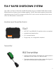
TS4-F RAPID SHUTDOWN SYSTEM Tigo’s TS4-F (or TS4-A-F, TS4-A-2F) and RSS Transmitter are a UL-certified PVRSS (Photovoltaic Rapid Shutdown System) when installed together. The RSS Transmitter supplies a keep-alive signal along one of the DC homeruns and the TS4-F units on each module will shut down when the Transmitter is switched off. Module-Level Power Electronics: TS4-F • NEC 2017 and 2020 690.
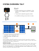
SYSTEM OVERVIEW: TS4-F TS4-F TS4-F • Module electronics are contained in the junction box, installed at the PV module factory. • Connected in series like regular modules • No additional wiring connections to make 1 2 3 Rapid Shutdown System Transmitter 1. Modules with integrated TS4-F 2. RSS Transmitter and RSS Core 3. Inverter The TS4-F requires a Tigo RSS Transmitter or inverter with built-in transmitter for operation.
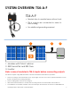
SYSTEM OVERVIEW: TS4-A-F TS4-A-F • Bracket clips to module frame without tools • TS4-A outputs are connected in series to form a string • No additional grounding required 1 2 3 Tigo Rapid Shutdown TS4-A-F 4 - 123A DO NOT DISCONNECT UNDER LOAD Rapid Shutdown System Transmitter 1. Modules with TS4-A-F add-on 2. RSS Transmitter and RSS Core 3.
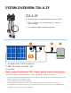
SYSTEM OVERVIEW: TS4-A-2F TS4-A-2F • Bracket clips to module frame without tools • TS4-A outputs are connected in series to form a string • No additional grounding required 1 2 3 Tigo Rapid Shutdown TS4-A-2F 4 - 123A DO NOT DISCONNECT UNDER LOAD Rapid Shutdown System Transmitter 1. Modules with TS4-A-2F add-on 2. RSS Transmitter and RSS Core 3.
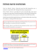
TESTING RAPID SHUTDOWN TS4-F (or TS4-R-F, TS4-A-F, TS4-A-2F) and the RSS Transmitter are a solution to meet NEC 690.12 Rapid Shutdown requirements. TS4-F, TS4-R-F, TS4-A-F, and TS4-A-2F units automatically enter rapid shutdown mode when the RSS Transmitter is switched off and resume energy production when power is restored to the RSS Transmitter. Wait 60 seconds after rapid shutdown activation before disconnecting DC cables or turning off DC disconnect.
TROUBLESHOOTING BASICS TS4-F, TS4-R-F, TS4-A-F, TS4-A-2F, Tigo RSS Transmitter Troubleshooting this kind of system will require basic PV system knowledge and the ability to measure voltage. Before and during all service or maintenance activities on a PV array, the service technician should inspect equipment for visible damage. Any physical damage on PV modules, wires, connectors, or MLPE units should be checked for and acted upon.
TROUBLESHOOTING - STRING-LEVEL Issue String has no DC voltage (0.0V) Description TS4-F, TS4-R-F, and TS4-A-F should pass 0.6V per unit when the string is not connected to an active transmitter. If the output voltage is measured at 0.0V on a string, there is an open circuit condition. This is most often caused by a wiring issue within the string. Step 1 Verify the string has been correctly disconnected from the inverter and any parallel strings before the individual string voltage is measured.
TROUBLESHOOTING - MODULE-LEVEL Issue TS4-F integrated module has no DC voltage (0.0V) Description An integrated TS4-F unit should pass 0.6V when connected to a PV module and the string is not connected to an active transmitter. If an output voltage of 0.0V is measured on a TS4-F integrated module, a connection problem between the junction box base and the cover might be present. Step 1 Shut down the system, wait 60 seconds and disconnect the output leads of the unit. • If 0.
TROUBLESHOOTING - MODULE-LEVEL Issue TS4-R-F / TS4-A-F has no DC voltage (0.0V) Description A TS4-R-F / TS4-A-F / TS4-A-2F unit should pass 0.6V when connected to a working module and the string is not connected to an active transmitter. If an output voltage of 0.0V is measured on a TS4-R-F / TS4-A-F / TS4-A2F unit, it is possible there is a wiring issue, the unit has a problem, or the module has an issue. Step 1 Shut down the system, wait 60 seconds and disconnect the output leads of the unit.
TROUBLESHOOTING - MODULE-LEVEL Issue TS4-F / TS4-R-F / TS4-A-F / TS4-A-2F with active RSS Transmitter not passing full voltage Description The RSS transmitter is turned on and appears active, but the TS4-F, TS4-R-F ,TS4-A-F, or TS4-A-2F are not passing full PV module output voltage to the string. This is most often caused by the transmitter’s signal being interrupted. The interruption may be related to improper installation of the RSS Transmitter, transmitter failure, or improper string/inverter wiring.
TROUBLESHOOTING - SYSTEM-LEVEL Issue Reduced Production Description The performance of a solar array shows a visible reduction in production within a short period of time, not related to changing environmental factors like weather, insolation, etc. Step 1 Prior to troubleshooting the system components, external factors should be ruled out.
TROUBLESHOOTING - RSS TRANSMITTER Issue Tigo RSS Transmitter operation check Description When AC power is connected to the power supply unit, the RSS Transmitter should be turned on and the PLC keep-alive signal should be activated. The TS4-F or TS4-R-F / TS4-A-F / TS4-A-2F units will then provide full voltage to their string. Operation When AC power is connected to the power supply unit, the Tigo RSS Transmitter should be turned on and signaling be activated.
TROUBLESHOOTING CONTACTING TIGO SUPPORT Before contacting Tigo Support In any event where the inverter has an error code, please check the inverter’s operation and safety manual for troubleshooting guidance or contact the inverter manufacturer for further assistance. Should an issue persist after following the troubleshooting steps as described in this manual, a summary of the performed tests and a list of system related information detailed below should be provided to Tigo support.
For more details on troubleshooting and servicing solutions powered by Tigo, please visit: • Tigo Academy • Resource Center For sales info: sales@tigoenergy.com or 1.408.402.0802 For product info: www.tigoenergy.com/products For technical info: training.tigoenergy.com For service info: support.tigoenergy.com For additional info and product selection assistance, use Tigo’s online design tool at www.tigoenergy.com/design Tigo Energy, Inc.