
RSS Transmitter Troubleshooting

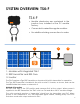
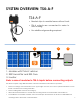
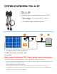

SYSTEM OVERVIEW: TS4-F
6
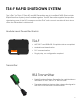
The TS4-F requires a Tigo RSS Transmitter or inverter with built-in transmitter for operation.
The Tigo RSS Transmitter is installed in line with a solar PV inverter, as shown, and can be
installed inside the inverter or external to it.
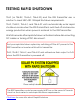
Method of Operation
All TS4-F units start in the OFF position and measure 0.6V at the output. When power is
supplied to the RSS Transmitter, the TS4-F units turn ON and allow full PV module voltage.
The units constantly receive a “keep-alive” signal from the transmitter over PLC. When
power to the transmitter is cut, this keep-alive signal ceases, sending every TS4-F into
shutdown mode with output reduced to 0.6V.
Rapid
Shutdown
System
Transmitter
1 2 3
1. Modules with integrated TS4-F
2. RSS Transmitter and RSS Core
3. Inverter
• Module electronics are contained in the
junction box, installed at the PV module
factory.
• Connected in series like regular modules
• No additional wiring connections to make
TS4-F
TS4-F