
User Manual

To mount to wooden pole or wall, install two screws
through the housing mounting tabs. Secure them to
the required service.
It also contains a magnetic base for mounting to
metallic surfaces.
Prepare and Route Cables, Grounding
Route the central office (c.o.) wire to the housing.
If the cable is shielded, remove 1” of sheath and
attach the ground lug to the shield.
Route the subscriber wire to the housing.
Strip the outer jacket insulation from the subscriber
wire, exposing the insulated conductors.
Connecting Sealed Subscriber Bridge to Sealed
Station Protector (where applicable)
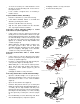
Using a 216 tool, raise the station protector driver by
turning the bolt counterclockwise until the bolt spins
freely, indicating the driver is in the “up” position. Insert
the subscriber bridge conductors into the proper small
top wire ports of the station protector until fully seated
(approx. ¾” or 20mm). Do not strip insulation from
conductors (Figure 2).
While holding the subscriber bridge conductors into
the station protector driver, turn the driver bolt
clockwise and return the driver to the “down” position
(Do not overtighten.) Pull lightly on the subscriber
conductors to verify connection (Figure 3).
Connecting Central Office Wire to Sealed Station
Protector
Using a 216 tool to raise the driver bolt of the station
protector until it spins freely, indicating that the driver
is in the “up” position (Figure 3).
Insert the c.o. wire pair into the two large bottom ports
of the protector (Figure 3) until fully seated.
While holding the c.o. wires into the station protector
driver, turn the driver bolt clockwise and return the
driver to the “down” position (Figure 3). (Do not
overtighten.)
Pull lightly on all wires to verify connection.
Connecting Station Wire to Sealed Subscriber Bridge
Open the subscriber bridge cover to gain access to
top/bottom terminating rockers. Note the lid can be
removed from the base of ease of wire installation
(Figure 4).
Open one unused wire rocker (Figure 4).
Insert the wire pair into the TIP (“T” or Green) and
RING (“R” or Red) rocker until fully seated (approx. ½”
or 13mm). (Do not strip insulation from wire.) Note
that if the wire was previously connected to the bridge,
trim away the last inch (25mm) or so of wire, removing
the area previously scored by the connectors (Figure
4).
Press thumb firmly on rocker until it snaps shut. Route
wires under lid (Figure 5). Repeat as required.
Pull lightly on all wires to verify connection.
Perform all customary tests.
TOP LEFT TERMINATING ROCKER
(VOICE CIRUCITS ONLY)
TOP RIGHT TERMINATING
ROCKER (DIGITAL CIRUCITS
ONLY)
BOTTOM TERMINATING ROCKERS
(VOICE CIRUCITS ONLY)
WIRE GUIDES
TIP & RING
CUSTOMER TEST JACK
CUSTOMER LOCK HASP
CUSTOMER SECURITY COVER
LOCKING HINGE
TEST PORTS
Figure 2
Figure 3
Figure 4
Figure 5