
Manual


12. Terminate additional pairs to rockers as
required.
13. Assure all rockers are in the down position
and close customer security cover.
CBM Wiring (Screw Terminal Connections)
1. For binding post terminations, strip customer
wire ½ inch and terminate to the
corresponding Tip (green) and Ring (red)
screw terminals.
Figure 7
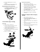
Central Office Signal Testing
Sealed CBM
1. Open customer security cover.
2. Insert RJ-11 plug into customer test jack to
isolate telco and customer wiring.
3. Using an ohmmeter, insert test clips into test
ports as shown (See Figure 8).
4. If continuity is measured, a “short” may exist in
the customer premise.
5. Wires are ok if meter shows a reading.
Figure 8
Screw Terminal Connections
1. Open customer security cover.
2. Insert RJ-11 plug into customer test jack to
isolate telco and customer wiring.
3. Using an ohmmeter, check for continuity
between the conductive heads of the tip
(green) and ring (red) screws.
4. If continuity is measured, a “short” may exist in
the customer premise.
5. Wires are ok if meter shows a reading.
6. Close customer security cover and inform
customer.
Customer Telephone Wire Integrity
Testing
1. Open customer security cover.
2. Using a working telephone, insert the
telephone RJ-11 plug into the customer test
jack (See Figure 9).
3. Wait a few seconds, lift receiver, and listen for
tone.
4. If dial tone is not present, then contact central
office service provider.
5. If dial tone is present, then a problem exists in
the customer telephone wires.
Figure 9