Time Electronics 1010 DC Voltage Calibrator Technical Manual V1.1 20/04/09 Time Electronics Ltd Botany Industrial Estate, Tonbridge, Kent, TN9 1RH Tel: +44(0)1732 355993 Fax: +44(0)1732 770312 Email: mail@TimeElectronics.co.uk Web Site: www.TimeElectronics.
C ontents 1. 2. Introduction ............................................................................................................ 3 1.1. General Description................................................................................................ 3 1.2. Specifications ......................................................................................................... 3 1.3. Power Unit ...............................................................................................
1. Introduction 1.1. General Description The 1010 is an accurate battery/mains powered voltage calibrator sourcing up to 10 volts in 5 ranges with a resolution up to 0.01uV. A precision zener reference diode is used as a basic reference source and low temperature coefficient resistors are used. Power is provided by a mains/rechargeable battery power unit. A front panel indicator monitors the battery condition.
1.3. Power Unit The 1010 is supplied with a mains/battery power unit. This can be configured when ordered for either 115V or 230V AC, 50/60Hz. See section 2.7.3. 1.4. Circuit Description The calibrator employs a temperature compensated zener diode as the basic reference source.
2. Operation 2.1. Operating Procedure Operation of the 1010 is self explanatory from the front panel controls and specification. Normal precautions concerning overload and incorrect range etc., should be observed. Battery condition should be checked on the front panel display before and during use. For quick zeroing of output set the Polarity switch to ‘OFF’. This applies a short on the output terminals 2.1.1.
2.3. Output noise The electrical noise on the output voltage consists of chopper intermodulation, thermal noise and random variations. Thermal noise becomes more significant on the lower ranges (see Thermal EMFS). In general the total noise level is less than 20ppm of setting +/- 2 uV for the 10v, 1v and 100mV ranges over the frequency range 0 - 10 Hz and less than +/- 0.2uV (010 Hz) for the lower ranges. Lower noise levels can be obtained by connecting a low pass filter on the output terminals. 2.4.
2.7. Mains Power Unit 2.7.1. Type PU2 The PU2 incorporates a rechargeable Nickel-Cadmium battery and electronics charge control circuitry. The circuitry is arranged to enable the PU2 to provide power directly from the mains if the mains input is connected or alternatively from the rechargeable battery if mains is not connected.
3. Constructional Layout Details The complete instrument assembly (except the Power Unit) is mounted on the front panel. A printed circuit board which carries the components and range switch is located immediately behind the front panel. The panel and p.c.b. can be removed as follows: 1) Remove Power Unit - located in instrument rear by 4 screws. 2) Disconnect supply - connected to power unit by 2 press stud connectors. 3) Remove front panel locating screws. 4) Withdraw front panel and p.c.b.
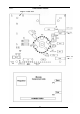
4. Recalibration This is performed with the panel and p.c.b. outside the case. Please see Fig. 1 for trimmer layouts. 4.1. Zero The F.E.T. chopper amplifier zero must be set before calibration can be done. The zero is set when the instrument is manufactured and under normal operation will not require readjustment. If a new circuit module is fitted or readjustment is found necessary, the following procedure should be adopted. 1) Connect power supply. 2) Select 99.999mV range. 3) Set all digits to zero.
Fig.
4.3. Calibration Procedure 1) Ensure zero has been set as in 3.2.1. 2) Connect power supply. 3) Select 999.99mV range, normal output polarity, and output digits to 99999. 4) Connect a suitable accuracy voltage standard with microvolt null meter to the output terminals. The voltage standard should have 0.005% accuracy or better and ranges from 10mV to 10V f.s. The null meter should have a resolution of better than 1uV and preferably have calibrated ranges. A high performance D.V.M.
5. Guarantee & Servicing Guarantee Period This unit is guaranteed against defects in materials and workmanship for a period of one year from its delivery to the customer. We maintain comprehensive after sales facilities and the unit can, if necessary be returned to us for servicing. During this period, Time Electronics Ltd will, at its discretion, repair or replace the defective items.