Time Electronics 5070 DuctorCal Ductor Tester and Micro-Ohmmeter Calibrator Technical Manual V5.1 19/03/12 Time Electronics Ltd Botany Industrial Estate, Tonbridge, Kent, TN9 1RH Tel: +44(0)1732 355993 Fax: +44(0)1732 770312 Email: mail@TimeElectronics.co.uk Web Site: www.TimeElectronics.
Contents 1. General Description ........................................................................................... 3 2. Specifications ..................................................................................................... 4 3. 4. 2.1. Technical Specification ...................................................................................... 4 2.2. General Specification .........................................................................................
1. General Description The 5070 is a portable instrument suitable for calibrating high current Ductor Testers and Micro-Ohm meters. It contains 5 sets of high current rating standard resistors which simulate the resistance being measured. It has full 4 terminal capabilities with extra large terminals for the current connection. Gold plated terminals are used throughout to reduce contact resistance and thermal emfs (for dc based instruments).
2. Specifications 2.1. Technical Specification Range Current Accuracy 50, 100, 150, 200µΩ 200A 0.8% 0.5, 1, 1.5, 2mΩ 100A 0.5% 5, 10, 15, 20mΩ 30A 0.2% 50, 100, 150, 200mΩ 10A 0.1% 0.5, 1, 1.5, 2Ω 3A 0.1% The currents shown are the continuous rated currents for both AC and DC. Higher currents can be used intermittently as supplied by pulse driven instruments.
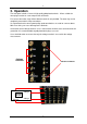
3. Operation The front panel contains 5 rows of high quality gold plated terminals. All are suitable for 4mm plug insertion on screw compression connectors. For current connection, large 25mm diameter terminals are provided. The outer ring can be completely removed for clamp connections. It is important that the correct good quality spade terminations are used for currents above 50A since arking can cause damage to the terminals.
3.1. Example Connection In the example below a T & R DSM200 is connected for calibration of the 200A range. 3.2. Operating Precautions If thermal emfs are suspected the voltage terminal output should be checked on all positions with zero current flowing (current leads disconnected). The zero position is checked with the voltage potential leads from the unit being calibrated, connected together on the 5070’s ‘0’ voltage terminal.
4. Guarantee & Servicing Guarantee Period This unit is guaranteed against defects in materials and workmanship for a period of one year from its delivery to the customer. We maintain comprehensive after sales facilities and the unit can, if necessary be returned to us for servicing. During this period, Time Electronics Ltd will, at its discretion, repair or replace the defective items.