Model: HF1 Installation & Operating Instructions High Frequency Sensor
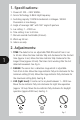
1. Specifications: 1. Power: AC 220 ~ 240V 50MHz. 2. Sensor Technology: 5.8GHz High Frequency. 3. Switching capacity: 1000W Incandescent or Halogen / 500VA Fluorescent or Low Energy. 4. Angle of coverage: 360° with 160° angle of aperture. 5. Lux setting: 1 ~ 2000 Lux. 6. Time setting: 3 sec to 30 min. 7. Manual override: Switchable (4 Hours). 8. Warm up: 60 sec. 9. Indoor use only. 2. Adjustments: 1 1. TIME: The detector has an adjustable TIME ON control from 3 sec. to 30 min.
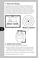
. Detection Range: The integrated HF sensor emits high-frequency electromagnetic waves (5.8GHz) and receives their echo, any change in echo is perceived by the sensor and will indicate the presence of a person(s) or animal(s). A microprocessor triggers almost without any delay and will activate the connected lights or applications. Detection is able to pass through glass, doors and around partitions with 360 degree coverage. See Fig. D, E. 6m 2 Min. 6m h=2.4~3m Fig. D Fig. E Max. 3.6m L’ N L N Min.
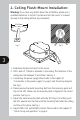
. Ceiling Flush-Mount Installation: Warning: If you have any doubts about the installation, please ask a qualified electrician to install it and ensure that the sensor is screwed securely to the ceiling without any movement. Ø112mm Ø112mm Fig. F Fig. G 3 1. Determine the best location for the sensor. 2. Drill a hole of 112mm in diameter in the ceiling. The thickness of the ceiling must be between 5 and 25mm. See Fig. F. 3. Connecting the power supply.
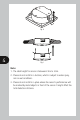
Fig. H L’ N L N L’ N L N 4 Fig. I Note: 1. The ideal height for sensor is between 2.4m to 3.0m. 2. Please do not install in a location, which is subject to water spray, rain or wet conditions. 3. Please do not install in a place where the sensor’s performance will be masked by metal objects in front of the sensor. It might affect the total detection distance.
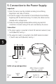
5. Connection to the Power Supply: Important: 1) Note: This sensor must be installed according to local Wiring Regulations and Code of Practice. 2) Ensure the supply is disconnected at the distribution board before beginning with the electrical wiring. If in doubt, the cables must be checked with a voltage tester. 3) Study the wiring diagram below before making any electrical connections. Incorrect wiring of the unit could destroy the sensor.
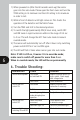
1) When powered on (after the 60 seconds warm up) the sensor goes into the auto mode. Please open the front cover and turn the TIME setting to its minimum and the LUX setting to its maximum in order to test. 2) Walk in front of detector until light comes on. This checks the operation of the detector and the field of view. 3) Turn the TIME and LUX to the desired positions. 4) To switch the light permanently ON (4 hours max), switch OFF and ON twice in rapid succession within in the range of 0.5 sec to 2 sec.
3 Year Guarantee In the unlikely event of this product becoming faulty due to defective material or manufacture within 3 years of the date of purchase, please return it to your supplier in the first year with proof of purchase and it will be replaced free of charge. For years 2 and 3 or any difficulty in the first year telephone the helpline on 020 8450 0515. For assistance with the product please contact: HELPLINE 020 8450 0515 or email helpline@timeguard.