
User guide


5
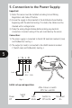
5. Connection to the Power Supply:
Important:
1) Note: This sensor must be installed according to local Wiring
Regulations and Code of Practice.
2) Ensure the supply is disconnected at the distribution board before
beginning with the electrical wiring. If in doubt, the cables must be
checked with a voltage tester.
3) Study the wiring diagram below before making any electrical
connections. Incorrect wiring of the unit could destroy the sensor.
Connection:
1) The mains supply is connected to the AC IN terminals marked L (Live)
and N (Neutral). See Fig. J.
2) The output (or Load) is connected to the LOAD terminals marked
L’ (Switch Live) and N (Neutral). See Fig. J.
L’ N L N
L’ N L N
L’ N L N
L’ N L N
Fig. J
AC IN
220V ~ 240V
Load
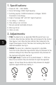
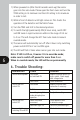
Initial set up and operation:
Switch
Power On Auto Switch 2 x Permanent
Off Mode Off and On On
After 4 Hours or switch
Off 2 Sec. and ON