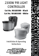
Cat No. NSLB2000 - Black Cat No.
Ge F lAMp TYpe NSLB2000 PIR light controller500w - Black 1 2300w DeTeCTiOn AnGle DeTeCTiOn RAnGe 180º 12m MAXiMUM ADJUSTABle ADJUSTABle eleCTRiCAl inSTAllATiOn DiMenSiOnS - MM WeATHeRpROOF DeTeCTiOn AnGle Helpline DeTeCTiOn RAnGe X:190 Y:250 Z:170 Y lAMp TYpe piR SWiTCHinG 2300w DeTeCTiOn AnGle 500w MAXiMUM 180º 230w piR SWiTCHinG VOlTAGe 2300w DeTeCTiOn RAnGe MAXiMUM 12m MAXiMUM ADJUSTABle eleCTRiCAl inSTAllATiOn DiMenSiOnS - MM ADJUSTABle inSTAllATiOn WeATHeRpROOF TiMe On
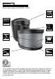
SECTION ONE GENERAL INFORMATION The unit utilises passive infrared technology to detect heat radiation of moving human bodies. Upon detection, the attached lighting load will illuminate for a user-determined time period. An integral daylight sensor ensures night-only operation if required. PARTS INCLUDED - PIR Sensor unit. - Instruction manual. Please keep safe for future reference. - Accessory Pack. TOOLS & PARTS NEEDED - Electric/hand-held drill & bits.
SECTION THREE INSTALLATION After choosing a suitable location (see previous section) install the unit as follows: The unit is suitable for connection to a 230 V ac 50Hz electricity supply. It is suggested that 3-core round flexible cable of 1mm2 gauge is used. An isolating switch should be installed to switch the power to the unit ON & OFF.
SECTION FOUR COMMISSIONING AND OPERATION WALK TEST PROCEDURE The sensor will rotate from left to right, and tilt forward or backward. Adjust the sensor to point in the required direction and angle down to limit forward range as required. The unit can be set up in daylight or at night. Set the time adjustment to the minimum (fully anti-clockwise) and the light threshold to maximum (fully clockwise), (see diagram C). Turn the power to the unit on. The lamp will illuminate for approximately 30 seconds.
MASKING THE SENSOR LENS To restrict the sensor coverage, preventing detection in unwanted areas, mask the sensor lens using the masking label provided (see diagram D). The top section of the lens covers long range detection, the bottom covers short range. Similarly the left and right lens sections cover the left and right detection areas respectively. MANUAL OVERRIDE MODE The light can be switched on for longer time periods by use of the Manual Override Mode.
SECTION SEVEN TROUBLESHOOTING GUIDE PROBLEM SOLUTION ❏ Lamp stays ON all the time night and day. Check wiring connections. Wires to L and L1 terminals may be transposed. ❏ Lamp stays ON all the time at night, or PIR keeps activating at random for no apparent reason. The unit may be suffering from false activation. Cover the sensor lens completely with black pvc tape. This will prevent the sensor from "seeing" anything.
A TOP VIEW 180º C Light Level Sensor Dusk Level Adjust Delay Time Adjust SIDE VIEW 2.
E CONNECTION DIAGRAM N L Terminal Block Mains Supply Backplate Isolation Switch F 2 Step 2 Grasp here and push in direction 2 1 Step 1 Insert flat blade screwdriver under tab and lever in direction 1
For assistance with the product please contact:- Helpline 020-8450-0515 or email helpline@timeguard.com For a product brochure please contact: Timeguard Ltd. Victory Park, 400 Edgware Road, London NW2 6ND Tel: 020-8452-1112 or email csc@timeguard.com A Group company 67-058-303 (Iss.