Model: PDSM1500 Installation & Operating Instructions 360º Surface Mount Ceiling PIR Light Controller
Considerate Lighting pollution bythe incorrectly installing a unit an or area Please be caused aware of annoyance over-lighting over-lighting an area can be limited by carefully can cause to your immediate neighbours. Light considering the location and position of your unit pollution caused by incorrectly installing a unit or 1. Introduction befo re installation.
CC C to to to or or or Lux Time On Time On Time On Time On ea ea ea Lux Dusk/Dawn Lux Lux Dusk/Dawn Dusk/Dawn Dusk/Dawn setting setting D D D 2 2 2 3 3 Mains Mains Supply Mains Supply IN Supply IN IN e e etive tive tive EE E Connect Earth wire Connect Earth wire to wall box Earth terminal Connect Earth wire to wall box Earth terminal to wall box Earth terminal LL L N N N L1 L1 L1 Switched Switched Load Switched Load OUT Load OUT OUT Wall box Wall box Wall box
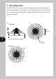
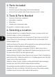
2. Parts Included • • • PIR Sensor unit. Instruction manual. Please keep safe for future reference. Accessory Pack. Includes cable clamp wiring cover and 2 x screws. 3. Tools & Parts Needed • • • • Terminal or Electricians screwdriver. Small philips screwdriver. Wire cutters. Suitable mains interconnect cable. This product is suitable for indoor use only. 4. Selecting a Location The motion detector has a number of detection zones, at various vertical and horizontal angles as shown (see diagram A).
. Installation IMPORTANT Switch off the electricity at the fuse box by removing the relevant fuse or switching off the circuit breaker before proceeding with the installation. All fittings should be installed by competent person in accordance with IEE Wiring Regulations (BS7671) Do not attempt to install if you are suffering from nausea or dizzy spells or on medication with similar side effects. If in any doubt, consult a qualified electrician.
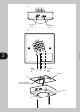
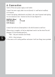
. Connection Switch off the main power supply or wall switch. Connect the mains supply cable Live core (brown) to L and Neutral core(Blue) to N terminal. Connect the lighting cable Neutral core (blue) to the same N terminal and Lighting Live core (brown) to the L1 terminal on the unit (see diagram D):NEUTRAL (Blue) LIVE (Brown) LIVE (Brown) N L1 Load L Connect the Earth wire (Green/yellow) to the Earth terminal on wall box.
. Setting up Walk Test Procedure TIME – Fully anti-clockwise (Test Mode) DUSK – Fully clockwise The unit will now operate during daytime as well as at night, illuminating the lamp for approx. 5 seconds each time. This allows testing to be carried out to establish whether the sensor is covering the required area. The lamp will immediately illuminate as the unit goes through its “warm-up” period. After approximately 1 minute the lamp will extinguish.
The DUSK control determines the level of darkness required for the unit to start operating. The setting is best achieved by the procedure below: Set the DUSK control knob fully anti-clockwise. The unit will now start operating at dusk.
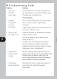
8. Troubleshooting Guide Problem Solution • Lamp stays ON all the time at night. Cover PIR lens with a thick cloth. If the light turns out, check detection area for heat or reflective source. If the light stays on, check wiring. See Connection. • PIR keeps activating for no reason (at random). Turn off at the isolation switch. Turn back on again after 30 seconds. Leave for approximately 15 minutes. • PIR sensor will not operate at all.
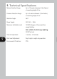
9. Technical Specifications Motion Detection Range: Up to 10 metres diameter (4.5m Radius) at mounting height of 3m Presence Detection Range: Up to 3 metres diameter (1.5m Radius) at mounting height of 3m Detection Angle: 360º Power Supply: 230 V AC ~ 50Hz Maximum Switchable Load: 1500W Halogen or Fluorescent/low energy lighting. Not suitable for discharge lighting.
3 Year Guarantee In the unlikely event of this product becoming faulty due to defective material or manufacture within 3 years of the date of purchase, please return it to your supplier in the first year with proof of purchase and it will be replaced free of charge. For years 2 and 3 or any difficulty in the first year telephone the helpline on 020 8450 0515.
HELPLINE 020 8450 0515 or email helpline@timeguard.com For a product brochure please contact: Designed in the U.K. 67-058-426 Zerofour – September 2011 Timeguard Limited. Victory Park, 400 Edgware Road, London NW2 6ND Sales Office: 020 8452 1112 or email csc@timeguard.