Model: TGBT5 Installation & Operating Instructions Electronic Boost Timer
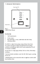
1. General Information Boost time LED’s 4 3 2 1 Boost Boost Button 2 Fig. 1 TGBT5 Front Panel Contents 1 2 1 1 TGBT5 Boostmaster. 3.5mm screws. Bag containing: 2 screws, cable blank and cable clamp. Instruction leaflet. The TGBT5 is a boost timer giving a range of boost times from 1hr to 4hrs covering the majority of requirements for heating, ventilation and lighting (a light switch may be replaced by this unit if a neutral is available).
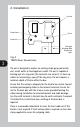
2. Installation Live out Neutral out Live in Neutral in Cord grip/ blanking plate fixing screw holes 3 Fig. 2 TGBT5 Rear Connections The unit is designed to replace an existing single gang connection unit, socket outlet or fixed appliance outlet. The unit is capable of forming part of a ring main (the terminals can accept 2 x 2.5mm sq. cables) or terminating a spur off the ring main. The unit requires a minimum depth of 25mm within the box.
3. Operation The required boost time is selected by pressing the button marked Boost repeatedly.
4. Specifications This product complies with: LVD Directive 72/23/EEC. EMC Directive 89/336/EEC. and relevant clauses of the following standards: Permissable loads: BS EN 60730-7-2:1992; Particular requirements. Timers and time switches. 13A resistive. 5A inductive. 1000W filament lamps. 500W fluorescent lighting. 100W low energy lamps. For other loads refer to technical service on 020-8450-0515. 5 Operating ambient temperature: 0 to +40ºC. Operating voltage: 230VAC, 50Hz.
In the unlikely event of this product becoming faulty due to defective material or manufacture, within 3 years of the date of purchase, please return it to your supplier in the first year with proof of purchase and it will be replaced free of charge. For years 2 and 3 or any difficulty in the first year telephone our helpline on 020 8450 0515. for assistance with the product please contact: HELPLINE 020 8450 0515 or email helpline@timeguard.com For a product brochure please contact: Timeguard Limited.