No.
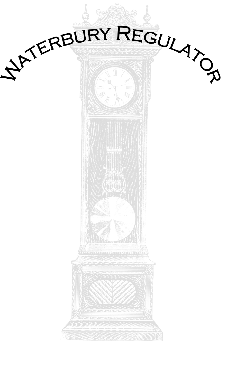
Waterbury Regulator No.
Table of Contents A History of the Waterbury Clock Company .................................................................. 1-2 The Process .................................................................................................................... 3-13 To Begin – The Take Down.....................................................................................3 At the Shop – Cleaning it up....................................................................................
A History of the Waterbury Clock Company (1857 – 1942) The Waterbury Clock Company, founded in March 5, 1857, began as a venture into the lucrative clock market by the ambitious Benedict & Burnham Corporation, heretofore the “B&B Corp.” Being a company specializing in the production of brass, and with clock movements being made of brass, the B&B Corp.
Until this point, Waterbury had been offering chiefly commonplace clocks. Their fame was truly made, however, when Waterbury, in 1892, began to build watches for the Ingersoll Company, who sold them as dollar watch alternatives to the expensive watches of the time. These became known as Ingersoll Watches, and were produced by an offshoot of the Waterbury Clock Company, the Waterbury Watch Company.
The Process To Begin – The Take Down The first day of work began on the morning of February 27, 2002; ninety years after the presentation of the clock to the school by the class of 1912. We [David LaBounty CMC, FBHI and Andrew LaBounty, Apprentice] received permission from Asst. Principal Mr. Carmody to remove the clock’s movement, dial, weight, and pendulum from the case and take it to our shop (then operating from home) for restoration. First, the pendulum was removed and placed to the side.
At the Shop – Cleaning it up The first step in restoring the movement was obviously to remove it from both the dial and the metal box that encased it. To achieve this, the taper pins that held the dial to the box and the screws affixing the movement to the box were all removed. In addition, the hands were removed to take the dial off. After the movement was taken out, several observations were made concerning the general state of the movement. It had indeed, been restored previously.
On Paper – Making a Map Before I could take the movement entirely apart, it had to be drawn so I would be able to put it together again with the gears in their proper places. To do this, I drew circles and numbered them in a hierarchy to display the order in which they went, then drew each individual gear to show “which way was up”.
Taking it Apart – And Determining Beats per Hour Finally, real work could begin with the gears themselves outside of the movement. To take the movement apart was a simple matter of taking out five screws and pulling the front plate straight upward to avoid bending any pivots or shafts. This done, the gears were exposed and could be removed and replaced as needed according to the drawing which showed which pivot hole was which.
Polishing Pivots – The Dreary Part Next, it was time to polish the bearing surfaces of the clock, called the pivots. The pivots are the ends of the gears that turn in the plate, and if they’re not polished, the clock will be sluggish and possibly stop. This is mostly due to the dirt that will be trapped in the scratches on the pivot plus the high amount of friction caused by the rough surface.
Major Project – The Escape Wheel “Nut” After the pivot polishing process was complete for all eight pivots, I progressed to “bushing” the pivot holes. A bushing is a small cylinder of brass with a hole in the middle designed to replace a worn hole. To replace a worn hole, one uses a hand reamer (a small handheld tool that when twisted, can cut a hole quickly to an exact size) Hand Reamer vs.
inserted the smaller end of the threads (which I filed down) into the rim of brass that was the head of the nut and peened the end down by hammering it flat so that it wouldn’t slip when it was screwed in. After the new threads were stuck tight in the rim, I drilled a hole through them, creating a threaded bushing, and eventually sized that hole to fit the escape wheel pivot. When I drilled the hole, I chucked up on the threads instead of the rim so that I could drill the hole centered in the threads.
Polishing the Pivot Holes – Everything’s so Shiny! Since most of the hard part was completed, I was happy to move on to polishing pivot holes, as it meant the pivots would soon be in them and turning again. Unfortunately, the pivot holes take a little while to clean, though they go much faster if the bushings are done right.
rotation of the escape wheel. The lock face is the portion of the pallet that stops an escape tooth. There are also lift angles on the ends of the pallets (the lift faces) that drive the pendulum sufficiently to keep the clock running, and are subject to wear (as are the lock faces). My first goal was to measure the lift angles. To do so, I measured the pallets from the center of the pivot to the mid-point of the pallet thickness. Dividing this by two gave a value of half of the length of the pallet arm.
I used the finer adjustment knob nearer to the bottom of the leader to finish the adjustment. After setting the beat, I set the rate, or the quickness of the tick-tocks. This was done using the nut at the bottom of the pendulum. I used the same timing machine to measure how many beats the Fine Beat Adjuster clock made per hour, which I found above Rate Adjuster to be 3600. I tweaked the nut until the measurement was just that or very close to 3600.
Conclusion – And Thanks I really enjoyed working on this lovely clock, and I’m honored to be a part of the history begun by the esteemed Class of 1912. Olathe North truly has one of the great clocks in existence today, and I trust it will be around for another 90 or 100 years. I would like to thank Mrs. Dorland and Mr. Carmody for their support in allowing me to restore the clock, and I’d also like to thank Ms.
Care and Maintenance This Section by: David LaBounty, Certified Master Clockmaker AWI, Fellow BHI Winding This clock should be wound on a regular basis and once per week is acceptable. The clock may run for twelve to fourteen days but it is important to avoid having the weight settle on the bottom of the case. Damage to the escape wheel teeth could occur if all power is off of the train (as in the weight resting on the bottom of the case) and the pendulum continues to swing.
Rating Rating the clock means adjusting the time keeping so the clock neither gains nor loses time while it is running. This is done by raising or lowering the pendulum bob using the rating nut on the bottom of the pendulum. Stop the pendulum to make all adjustments and then gently start the pendulum swinging when done. Minimize the amount of contact with the polished brass since the oils on a person’s hands will leave dark splotches. Touch the edges when at all possible or use a rag over the hand.
The wood case may be dusted with a slightly damp cloth and it is generally not advisable to apply a dusting agent. Wax buildup and dirt will darken the case with years of use and could destroy the original finish. Moving the Clock At some point it may become necessary to relocate the clock. This may be done safely if certain measures are taken. 1. Allow the clock to run until the weight is well down in the case but not touching the bottom. 2.
to place shims under the front of the clock to force it to lean back against the wall. If this isn’t done, the clock may sway or worse yet, fall over! The case must also be leveled side-to-side. Place a bubble level in the bottom of the case and shim one side or the other until the case is leveled. The case must be back against the wall and level side-to-side before the movement is reinstalled. Reinstall the movement, weight, and pendulum using the instructions for “Moving the Clock” as a guide.
Bibliography French Clocks: The World Over, Part One, by Tardy. Paris, 1949. pp. 10-30 Machinery’s Handbook 24th Edition, by Oberg, Jones, Horton, Ryffel. Edited by Robert E. Green. New York: Industrial Press Inc., 1992. pp. 1706-1707 Seth Thomas Clocks and Movements, by Tran Duy Ly. Virginia: Arlington Book Company, 1996. pp. 20-21 Waterbury Clocks, by Tran Duy Ly. Virginia: Arlington Book Company, 1989. pp. 13-20, pp.
Attachment A Repair Itemization: • Polish eight pivots • Clean four shafts • Straighten six escape wheel teeth • Draw (stretch) escape wheel teeth • Tip (machine) escape wheel teeth to true escape wheel • Straighten two pivots • Replace threads on hand nut • Install three bushings • Make one new movement screw (extra long and blued to match) • Realign (true) pillar posts • Close escape pallets to decrease entrance drop • Poise second hand • Tighten second hand on front escape wheel
Attachment B Tooth Count: • Hour Pipe = 80 teeth • Minute Wheel = 54 teeth • Minute Wheel Pinion = 10 leaves • Hour Wheel = 80 teeth • Cannon Pinion = 36 leaves • Main Wheel = 84 teeth • Second Wheel = 80 teeth • Second Wheel Pinion = 8 leaves • Third Wheel = 72 teeth • Third Wheel Cut Pinion = 12 leaves • Third Wheel Lantern Pinion = 8 leaves • Escape Wheel = 30 teeth • Escape Wheel Pinion = 8 leaves 20
Attachment C Original Sketch 21
Attachment D Other Sketches 22
23