
Instructions

© TIP Thüringer Industrie Produkte GmbH 2016/10/19
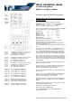
L1↑: incoming line conductor L1 of the circuit
L1↓: outgoing line conductor L1 to load
L2↑: incoming line conductor L2 of the circuit
L2↓: outgoing line conductor L2 to load
L3↑: incoming line conductor L3 of the circuit
L3↓: outgoing line conductor L3 to load
N: neutral conductor of the circuit
N: (neutral conductor of the circuit)
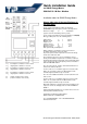
Quick installation Guide
for SINUS Energy Meters
SINUS 85 S0 / M-Bus / Modbus
Installation notes for SINUS Energy Meters
Always take note of the specifications on
the type label!
For an energy meter with the voltage specifications
3x230/400V on type label please note the following values:
Reference voltage U
n
= 3x230/400V
(3-phase four-wire alternating current system)
For an energy meter with the current specifications 0,25-5(85)
A on type label please note the following values:
Initial current I
st
= 0,02 A
Minimal current I
min
= 0,25 A
Suppressed
leakage current I
tr
= 0,5 A
Reference current I
ref
= 5 A
Maximal current I
max
= 85 A
with symmetrically loaded phases.
Always follow the specifications for the measurement
operating requirements on the type label.
As pre-fuse please install only in the measurement voltage
circuits fuses with max. 80 A.
The used wires have to be chosen regarding to current
density and installation requirements, so that the conductors
at all time don’t heat up to more than +55°C closer than 20cm
tot he energy meter. The load capacity of wires and cables is
defined in DIN VDE 0298-4.
The size of the current-, voltage- and neutral terminals is for
min 2,5 mm² and max 25 mm².
For the screws use a screwdriver type SL for slotted screws
with a size of 5,5mm x 1,0mm. The M5 terminal-screws
should be tightened with a torque of 2,5 Nm.
The size of the additional terminals is for min 0,25 mm² and
max 1,5 mm².
For the screws use a screwdriver type SL for slottet screws
with a size of 3,5mm x 0,6mm. The M5 terminal-screws
should be tightened with a torque of 0,4 Nm.
Wires with splitted core should end in a wire termination. The
torques for screws at clamping units are defined in DIN EN
60999-1.
Further important information for use af this device are in the
manual (delivered with the device).
TIP Thüringer Industrie Produkte GmbH
Bahnhofstraße 26 – D-99842 Ruhla
Tel.: +49 36929 64029 0 – Fax: +49 36929 64029 29
www.stromzaehler.de