Operation Configuration and Settings Planning and Installation (UK) Analogue Telephone System tiptel 2/8 USB tiptel
Contents General............................................................................................................... 4 Scope of delivery ......................................................................................................... 4 Notes on this Manual ................................................................................................... 4 Abstract ........................................................................................................................
Contents Activate/deactivate caller ID (CLIP) ........................................................................ 42 Set up call waiting signalling.................................................................................. 43 SMS terminal unit support...................................................................................... 44 Switching between day and night settings............................................................ 47 Set door bell signalling...............................
General General This Manual as well as the telephone system it refers to are subject to change without notice. An up-to-date version of this Manual is available as pdf document at www.tiptel.com. Texts and depictions in this document were prepared with utmost care, mistakes, however, cannot be rule out completely. The publisher will not assume any liability for errors or their consequences. © 2008 Tiptel.com GmbH Ratingen. All right reserved.
General depiction of all configuration options. But even without using the PC software most of the configuration can be made via the telephone 21 at port 1. Planning and installation The chapter 'Planning and installation' explains all connectors and ports, gives you advice on choosing the optimum location, the distribution of the telephone connections, and on what to keep in mind while mounting and installing the cables.
General • External line authorisation to be programmed individually per phone • Reservation of an external line • External line authorisation, semi or full • Authorisations for local, long distance, or abroad calls • Automatic fax reception with integrated and activated fax switch for external line 1 • Forwarding of telephone calls • Music on hold during forwarding process • Internal calls free of charge • Caller ID (CLIP) at all extensions • System telephone book with speed dial list, 10
General Accessories (optional) tiptel TSM 1, door intercom module (4+n-technology), no loss of any extensions Needed when using the pharmacy function when by ringing the door bell automatically a phone call is being placed to a predefined target and a connection is made with the door loudspeaker. Suitable terminal units Many of the features will be shown on the display of terminal units and can be activated directly via programmable telephone function keys.
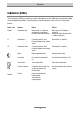
General Indicators (LEDs) The indicators (LEDs) provide you with information on the different operational states of the telephone system. The meaning of each indicator can be found in the table below. Name / icon Function LED on LED off Power Operational state Mains power on. Telephone system ready for operation. Flashing: Reset button pushed Mains power off. Telephone system off Emergency phone at external line 1 ready for operation L1 External line 1 Connection with ext.
General Overview of audio and call signals *Internal dialling signal as permanent signal in B, CH, E, F, GR, NL, P, UK Function details of audio signals Internal dialling signal You hear the internal dialling signal as soon as you pick up the handset. Now you can enter digits via the telephone's keypad and dial. Fast internal dialling signal You hear the fast internal dialling signal (special dialling signal), when your telephone is set to 'do not disturb' or call deflection has been activated.
Operation Operation In this User's Manual following icons for activating/deactivating of functions and features are used: Pick up handset Enter digits Using special keys R key (flash function) Hang up Notes Telephone number plan The telephone system uses a fixed not editable number plan. These numbers can be dialled from each telephone to activate the corresponding function.
Operation Telephone 7 Call Telephone 8 Call Door intercom system with TSM1 Connect with door Door opener with TSM1 Actuate door opener Call group 1 Call of call group Call group 2 Call of call group Call group 3 Call of call group Call group 4 Call of call group Person call ...
Operation Setting up a call Internal telephone calls Internal calls can be placed between any two extensions free of charge. The extensions' telephone numbers are 21, 22, . . . , 28. Example: Telephone 21 wants to call telephone 22. Telephone 21: Pick up handset. Internal dialling signal can be heard. Call an internal number. You hear the calling signal and the called telephone rings. In case names have been programmed for the extensions, NAME CLIP capable telephones will show the caller's name.
Operation line is busy you will hear the busy signal of your telephone system. In this case try again later or reserve an external line. In case your extension is not authorised to access an external line you will also hear the busy signal. Enter the number of the external subscriber. You will hear the calling signal. With a busy subscriber you should call again later. External subscriber: Pick up handset. You are connected to the external subscriber. Have your call. Hang up End of call.
Operation Query Incoming or outgoing calls can be put on hold in order to make a query. Example: Subscriber 22 has an external call and wants to ask subscriber 23 something. Telephone 22: Notify your conversational partner of the internal query Have your external call Initiate query. Internal dialling signal can be heard. Your conversational partner will be held in the telephone system and will hear music on hold. Dial number. You will hear the calling signal.
Operation Initiate query. You will hear the calling signal. Your conversational partner will be held in the telephone system and will hear music on hold. Dial number. You will hear the calling signal and the telephone you called will ring. In case names have been configured for the extensions NAME-CLIP capable telephones will show the callers name, if not only the callers number will be displayed. With a busy subscriber you hear the busy signal. Hang up then.
Operation Telephone 23: Pick up handset. Conversational partner on hold will be connected with telephone 23. Have your external call. Hang up. End of call. Forwarding external calls to external subscribers If you have two external lines available and you are authorised to perform an external forwarding you can put incoming or outgoing external calls on hold and forward them to another external subscriber with notification.
Operation Pick up handset of telephone 21. You will hear the internal dialling signal Dial code number . The external call will be disconnected. You will hear the acknowledge signal. Hang up. Disconnection is done. Summary of functions with an external line on hold Key sequence Function Requirement Initiate query.
Operation Subscriber features Following table describes the features available to you as subscriber at your extension. Pick up a call If you hear another telephone ringing you can pick up that call with your own telephone. Picking up a call is available for both, internal call and external call. Example: You hear another telephone ringing and you wish to take that call. Pick up handset.
Operation Call deflection to telephone 25: Code number 825 Call deflection to telephone 27: Code number 827 Call deflection to telephone 26: Code number 826 Call deflection to telephone 28: Code number 828 Deactivate call deflection Pick up handset. You will hear the internal special dialling signal Dial code number . By dialling code number 80 call deflection will be deactivated. You will hear the internal dialling signal. Hang up. Call deflection has been deactivated.
Operation Speed dialling With speed dialling external numbers saved to the central telephone book can be dialled on the external line automatically. Frequently used telephone numbers so can be used comfortably by all subscribers. Programming and maintenance of the central telephone book is made via the PC configuration software. Up to 100 entries can be saved. Each entry is assigned with a speed dial number between and , the name of the target subscriber and his/her telephone number.
Operation Example: Telephone 21 wants to talk with telephone 22. Telephone 22 is busy. Telephone 21 activates call completion on busy subscriber. Telephone 21: Pick up handset. You will hear the internal calling signal. Dial internal telephone number. Telephone 22 is busy. You hear the busy signal. Activate call completion on busy subscriber. You hear the acknowledge signal. Telephone 21: Hang up. Wait for call back Telephone22: Hang up. End of call. Telephone 21: Pick up handset.
Operation Hold External calls can be put on hold in your telephone system. The hold function will be initiated and terminated by pressing the key. Your conversational partner will hear music while he/she is on hold. In case you hang up while there still is a call on hold up to 45 seconds a call back will be carried out. In case the call is not being picked up again the telephone system will disconnect the caller on hold after those 45 seconds.
Operation Person call / urgency call The telephone system provides you with the option to call all extensions simultaneously with an individual ringing signal. Telephones with a standard ringing signal will play back the ringing signal in the same rhythm is will be turned on and off. There are seven individual call rhythms available for person or urgency calls which can be dialled via the code numbers 71 through 77.
Operation Pick up handset of one of the ringing telephones. You are connected to the internal subscriber. Have your call. Person calls / urgency calls can also be used to forward external calls with notification. Call groups Internal extensions can be put together to any call group and so can be reached under the same single telephone number. There are four different call groups available. One extension can be member of one or more call groups.
Operation Do not disturb Every extension can be programmed in such a way that the telephone will not ring on incoming calls (do not disturb). This function can be activated at your telephone by dialling the code number . You can still place calls yourself. With help of the PC configuration software you can grant or deny authorisation to activate this function individually for each subscriber. Activate 'do not disturb' Pick up handset.
Operation Prepare target telephone for room monitoring Telephone 23: Pick up handset. You will hear the internal calling signal Dial code number to prepare room monitoring. You hear an acknowledge signal. Place the handset beside the telephone so that the microphone opening points in the direction you want to monitor. Telephone is read for room monitoring. The room monitoring function can be deactivated at the target telephone simply by hanging up.
Operation If no CNG signal was detected a standard voice call will be assumed. The call will then be forwarded to those telephones configured as receiving telephones for incoming external calls. The telephone system will try for up to 55 seconds to set up a connection to an internal subscriber. At the same time the caller will hear a calling signal generated and sent by the telephone system. In case an incoming fax had been taken by a telephone this 'call' should be forwarded to the fax machine at port 4.
Operation Activating or deactivating the fax switch can only be carried out by the programming telephone or the PC configuration software. When using the programming telephone first you will have to enter the code number and then you will have to dial the coder number for switch on or for switch off.
Configuration and settings Configuration and settings This chapter addresses the installer and user of the telephone system. Settings and configuration options are described with which the telephone system can be adapted to the individual operation environment and the requirements needed. PC configuration software Easy, comfortable, and well arranged is the configuration via PC.
Configuration and settings Setting up the USB interface Connect the telephone system with one of your PC's USB ports by using the USB cable that came along with your telephone system and power up your telephone system then. You will see a prompt asking you to install a USB driver. This driver can be found on the CD-ROM Configuration Software, path D:\Driver\2-8 USB\USB.
Configuration and settings In addition to the functions you can configure via the programming telephone you can configure the following features via the PC configuration: • Authorisation speed dial • Authorisation 'do not disturb' • Authorisation 'pick up' • Authorisation 'person call' • Authorisation 'room monitoring' • Call deflection external • Names for extensions • Priority of external lines • Authorisation forwarding external/external • Selection of ringing signals • Definition o
Configuration and settings Several sequences of digits can be entered in a row. Successful inputs will be acknowledged by a continuous acknowledge signal. In case of an incorrect input an interrupted error signal is heard. the programming level will automatically be left 30 seconds after dialling the last digit or by simply hanging up. The configuration will be saved permanently to a non volatile memory. After a power line failure the configuration will still be there.
Configuration and settings The telephone system has been designed for use with 2 external lines. In case you are only using one external line it is strongly recommended to disable access to the second external line which is not in use. Activate/deactivate external line access Example: Access to external line 1 for telephone 23 shall be deactivated. 1. Telephone 21:Pick up handset You will hear the internal calling signal. 2. Dial code number . Programming level is on.
Configuration and settings Activate/deactivate external call signalling Example: External call signalling of external line 1 shall be deactivated for telephone 23. 1. Telephone 21: Pick up handset You will hear the internal calling signal. 2. Dial code number . Activate programming level. You hear the acknowledge signal. 3. Dial code number to deactivate external call signalling from external line 1 for telephone 23. You heart the acknowledge signal.
Configuration and settings Activate call forwarding 1. Telephone 21: Pick up handset You will hear the internal calling signal. 2. Dial code number . Activate the programming level. You hear the acknowledge signal. 3. Dial code number to activate the call forwarding. You hear the acknowledge signal. Call forwarding has been activated. External calls will be signalled at telephone 23 through 28 not before 15 seconds are over. 4. Hang up. Programming is done.
Configuration and settings 2. Dial code number . Activate the programming level. You hear the acknowledge signal. 3. Dial code number to activate automatic external line access for telephone 24. You hear the acknowledge signal. Telephone 24 now has automatic external line access. 4. Hang up. Programming is done. Once the handset of telephones 24 is being picked up this telephone will automatically be assigned with an external line.
Configuration and settings External line 1 2 Music on 841 842 Music off 851 852 Setting up blocked numbers The telephone system provides you with the option to block dialling of certain telephone numbers or digit sequences. 20 blocked numbers and 16 (+ fixed emergency numbers that cannot be deleted) exception numbers are available. With blocking activated first the dialled number will be verified.
Configuration and settings Example: Activate blocked numbers for telephone 24 1. Telephone 21: Pick up handset You will hear the internal calling signal. 2. Dial code number . Activate the programming level. You hear the acknowledge signal. 3. Dial code number to activate blocked numbers for telephone 24. You hear the acknowledge signal. Blocked numbers are activated for telephone 24. 4. Hang up. Programming is done.
Configuration and settings Dial lock for long distance calls on 8211 8212 8213 8214 8215 8216 8217 8218 8210 Dial lock for long distance calls off 8201 8202 8203 8204 8205 8206 8207 8208 8200 Entering blocked numbers Blocked numbers can be entered via the programming telephone 21. A DTMF telephone with CLIP function is recommended. For confirmation the number will be shown on the display. 20 blocked numbers with up to 6 digits each can be entered.
Configuration and settings 1. Telephone 21: Pick up handset You will hear the internal calling signal. 2. Dial code number . Activate the programming level. You hear the acknowledge signal. 3. Dial code number Enter code number for entry of blocked number. 4. Dial code number for memory index 05 For every blocked number a memory index number between 01 and 20 has to be used. In case one location will be re-used the old blocked number will be overwritten. 5. Hang up.
Configuration and settings 5. Dial digits of exception number The exception numbers can be digits 1,2..., *, and #. The maximum number of digits is 17. Further digits will be ignored. 6. Hang up. Entering the exception number is done. You will be called back. The exception number together with its memory index number will be shown on the display. 7. Telephone 21: Pick up handset You hear the acknowledge signal. For more entries proceed as described under item 3 8. Hang up.
Configuration and settings Table of pre-set exception numbers Memory index number D A CH NL B F 13 3651 14 30 15 0800 16 07024 5245 08365 91212 100 112 int Notes 112 cannot be deleted 17 110 112 117 18 112 122 118 101 15 cannot be deleted 19 133 144 112 17 cannot be deleted 20 144 18 cannot be deleted 112 Activate/deactivate caller ID (CLIP) Transfer of CLIP information can be activated/deactivated for every telephone individually.
Configuration and settings Telephone 21 22 23 24 25 26 27 28 all CLIP transfer on 351 352 353 354 355 356 357 358 350 CLIP transfer off 361 362 363 364 365 366 367 368 360 Set up call waiting signalling To indicate that there is another caller while you are already having a call on external line 1 or 2 you hear a call waiting signal, in case this function is activated.
Configuration and settings SMS terminal unit support Short messages (SMS) Details on the service 'SMS in the fixed net' SMS service allows sending short text messages to or receiving them from other terminal units. Those messages will not be sent directly to the other terminal unit, they will be transferred via the SMS service centre of your telephone company. A message can be up to 160 characters in length. Q requirement for using SMS caller ID (CLIP) support.
Configuration and settings service centre of www.sms-im-festnetz.de can be accessed via '09003266900' (SMS service centre 2). The way how to register is nit the same with every provider. Please contact your telephone company how this is done. With the telephone company German Telecom e.g., the first registration is free of charge*. You simply have to send an SMS with the message: "ANMELD" to the telephone number 8888.
Configuration and settings Receiving SMS It is possible to set up one extension (one port) for an external line to receive SMS messages. A terminal unit which supports SMS can then be operated at this port in order to receive incoming SMS messages. For each external line an individual SMS terminal device can be defined. It is necessary to configure external line access and external line signalling for SMS communication on this particular port.
Configuration and settings Deleting the defined SMS port Example: Delete configuration of telephone 21 for SMS communication on external line 1 1. Telephone 21: Pick up handset You will hear the internal calling signal. 2. Dial code number . Activate the programming level. You hear the acknowledge signal. 3. Dial code number . You hear the acknowledge signal.. SMS communication for external line 1 has been deleted. 4. Hang up. Programming is done.
Configuration and settings 4. Dial code number . You hear the acknowledge signal.. Day programme activated. LED off. You may programme settings for the features listed below, which then can be accessed via this dial code number. 5. Hang up. Programming is done. Following features can be affected by the day/night programmes: • • • • • • • External line signalling External line authorisation Dial lock for long distance calls (0...
Configuration and settings Telephone 21 22 23 24 25 26 27 28 all Door bell signalling on 591 592 593 594 595 596 597 598 590 Door bell signalling off 501 502 503 504 505 506 507 508 500 Set door opener authorisation The door opener can be actuated from every telephone connected to the telephone system in case the option door line module (TSM1) has been installed on the printed circuit board. This authorisation can be activated/deactivated individually for each telephone.
Configuration and settings Set duration of door opener actuation The duration of the door opener actuation can be programmed between 1 and 9 seconds. Programming can be carried out via telephone 21 according to the table below. In the factory default settings this duration is programmed as 3 seconds. Set duration Example: The duration shall be set to 5 seconds. 1. Telephone 21: Pick up handset You will hear the internal calling signal. 2. Dial code number . Activate the programming level.
Configuration and settings Programming can be carried out via telephone 21 according to the table below. In the factory default settings direct access to the door intercom system is deactivated. Activate/deactivate direct access to door intercom system Example: Direct access to door intercom system for telephone 23 shall be activated. 1. Telephone 21: Pick up handset You will hear the internal calling signal. 2. Dial code number . Activate the programming level.
Configuration and settings busy signal after the end of a call). Also it is not recommended to have a busy signal being played back at a door intercom system. Miscellaneous Following you will find some basic settings which are independent from the extensions in use. Setting of time and date The telephone system has its own internal clock with date and day of the week information for time controlled day/night programme and CLIP transfer.
Configuration and settings In case you only wish to update the clock simply hang up after entering the 4 digits for the time. After the call back you will hear the acknowledge signal. The time has been updated. Audio sample of music on hold With an external line on hold the subscriber will hear a piece of music. For testing purposes you can listen to that music on telephone 21 for 30 seconds. 1. Telephone 21: Pick up handset You will hear the internal calling signal. 2. Dial code number .
Planning and installation Planning and installation The chapter planning and installation describes the ports, helps you in choosing the right location, the distribution of the extensions, and gives you information on what to keep in mind during mounting and cable. The telephone system has been designed for operation with two external lines. In case only one external line is being used it is strongly recommended to block access to the external line which is not being used.
Planning and installation The telephone system may not be installed or operated in the following environments: • Outdoors • In damp rooms (bathroom, shower, swimming bath, ...) • Near to explosives • In location with direct sunlight • With ambient temperatures below 0 °C or above 40 °C • With heave vibrations • In dusty environment Environmental compatibility With intended use their will be no contact with any material that can be hazardous to your health.
Planning and installation Details on the connectors and ports of the telephone system Multi-pin connector for installing optional door module TSM1 8 pairs of screwing terminals for connecting extensions 21- 28 Reset button USB port Audio jack for ext. music on hold Western jacks to connect terminal units with RJ11 plugs directly. To be used for extensions 21 through 24 TAE jacks to connect terminal units with TAE plugs directly. To be used for extensions 21- 24 (Germany only) Jack ext.
Planning and installation 16 pin screwing terminal Terminals for all 8 internal subscribers. Two screwing terminals for every extension marked from 1 (for extension 21) through 8 (for extension 28). 4 western jacks RJ11 Western jacks for direct connection of terminal units, e.g. telephones with RJ11 cable connectors Western jacks are an alternative for extensions 21 through 24 instead of the screwing terminals. USB connector Connector for your PC to configure the telephone system Audio jack 3.
Planning and installation Tools and material needed • Hammer drill with 6 mm stone drill for wall mounting In case you wish to use the screwing terminals: • Screwdrivers of different size • Wire cutter, cable stripper • Telephone installation cable (e.g.
Planning and installation This is how to open the cabinet: 1 1 2 2 At the indicated areas (1) insert a slot screwdriver (4 mm) or a similar tool as far as it goes from bottom of the housing in the direction towards the top. Pull the screwdriver towards you (2) which will slacken the snap mechanism and lift the cover towards the back of the unit. Wall mounting of the telephone system Two rawlpugs and 2 screws are part of the scope of delivery.
Planning and installation Installing the cables for the connectors/wall outlets Your telephone system provides you with different options for connecting terminal units such as telephones, fax machines, or answering machines. Terminals that are not in the vicinity of the telephone system (e.g. in another room) will have to be connected by using telephone installation cables and separate connectors or wall outlets (not scope of the delivery).
Planning and installation Connecting terminal units e.g. cordless phone TAE jacks (Germany only) USB 21 22 23 24 ext. 2 ext. 1 Audio Western jacks e.g. comfort phone e.g. fax a) Terminal units that are not in the vicinity of the telephone system have to be plugged into the telephone jacks or wall outlets that have been installed before. b) Western jacks for the first extensions: Please use one particular jack exclusively for each terminal device in the centre of the jack array.
Planning and installation Connecting the telephone system to the external telephone lines External line 2 External line 1 Plug in the western plug of the external telephone line 1 in the corresponding western jack on the right and the one for line 2 in the corresponding western jack on the left hand side. And then connect those cable with the wall outlets connected to the telephone network of your telephone company.
Planning and installation PC connection For configuration and/or telephone book management you will have to set up a connection between the telephone system and a PC. For this please use the USB cable that came along with your telephone system and connect one end to with a USB port of your computer and the other end with the USB port of your telephone system (Please see also page 30).
Planning and installation to be able to do this the line reversal between connection to the external line and connection to the telephone system will be analysed. The power line failure indication is set up as follows: Install the telephone system as describer in chapter "Mounting the telephone system". The telephone system is in operation and connected to external line 1. • Install tiptel 272 at extension 21. • Set the MWI switch to position PR1 or PR2 whichever position results in the LED lighting.
Planning and installation Firmware update via the update server Push the reset button while in normal operation for 10 seconds. The power LED starts flashing. Once you release the reset button the telephone system will call the update server by using external line 1. The telephone number of the server is pre-set but - if necessary - can be changed via the PC configuration software's expert mode. LED L1 will go on and LED "Service" will indicate data communication. The firmware update will take appr.
Annex Annex Service You have purchased a modern product from TIPTEL.COM GMBH BUSINESS SOLUTIONS , developed and produced in Ratingen near Düsseldorf, Germany. Our highly modern production facilities ensure a consistently high level of quality. This is backed by our DIN EN ISO 9001 certification. If, however, problems do occur, or you have questions on operating the device, please contact your dealer. During the warranty period this dealer is your contact. Tiptel.
Annex Warranty Your contact for services included among the warranty obligations is the specialist dealer from whom you bought the device. Tiptel.com GmbH Business Solutions will grant a warranty of 2 years from the date of handover for the material and for the manufacturing of the telephone system. Initially, the purchaser shall have only the right to subsequent performance. Subsequent performance entails either repair or the providing of an alternative product.
Annex In Germany In Austria In Switzerland Tiptel.com GmbH Business Solutions Service Halskestraße 1 D-40880 Ratingen Tiptel GmbH Service Ricoweg 30/B1 A-2351 Wiener Neudorf Tiptel AG Service Bahnstrasse 46 CH-8105 Regensdorf In warranty cases, the equipment will be returned at Tiptel.com GmbH Business Solutions’ expense.
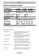
Annex Trouble shooting guide Problem Possible cause Solution When picking up the handset you do not hear the dialling signal. The Power LED is off. Power line outage. Check mains power, e.g. by plugging in another electrical device. AC adapter not plugged in. Plug in AC adapter Telephone connection not working. Check telephone connection and installation. Telephone defective. Try to use telephone with another port.
Annex External line signalling deactivated. Activate external line signalling (see page 33) Telephone system cannot be programmed via programming telephone 21. Programming telephone set to automatic external line access. All code numbers will be sent to the external line and not to your telephone system. After picking up the handset press the key to switch to internal and then dial the code numbers for the setting needed. Please listen for the acknowledge signal.
Annex CLIP correction Music on hold external line 1 Music on hold external line 2 Call signalling internal Call back signalling Calling signal from external line1 Calling signal from external line2 Receiving CLIP from external line 1 Receiving CLIP from external line 2 Call groups 1 - 4 Time control Ext. call deflection external line 1 Ext.
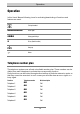
Technical data Technical data Analogue extension ports Feeding voltage: 40 VDC Feeding current: 24 mA +/- 10 % Call signalling voltage: 48V +/- 15 %, 50 Hz Frequency of audio signalling 425 or 440 Hz Max.
Index A P Audio signals....................................... 9 PC configuration software................. 29 PC connection................................... 63 Person call / urgency call .................. 23 Pick-Up.............................................. 18 C Call completion on busy subscriber . 20 Call deflection ................................... 18 Call groups........................................ 24 Caller ID............................................. 42 Calling signals..............
Tiptel.com GmbH Business Solutions Halskestraße 1 D - 40880 Ratingen Tel.: 0900 100 – 84 78 35* *(with costs) Vanity Tel.: 0900 100 – TIPTEL* Internet: www.tiptel.de International: Internet: www.tiptel.com Tiptel GmbH Ricoweg 30/B1 A - 2351 Wiener Neudorf Tel.: 02236/677 464-0 Fax: 02236/677 464-22 E-mail: office@tiptel.at Internet: www.tiptel.at Tiptel AG Bahnstrasse 46 CH - 8105 Regensdorf Tel.: 044 - 884 01 80 Fax: 044 - 843 13 23 E-mail: tiptel@tiptel-online.ch Internet: www.tiptel-online.ch Tiptel B.V.