
Owner's manual


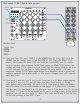


Lets take a break for a second to understand the nature of the pulse width
of a clock divider, and how the Trigger Riot lets you use it creatively.
Below are two drawings of the outputs of clock dividers: on the left are the
independent clock dividers, each one set to a different value, and on the right are
the sum of those dividers on the output of the Trigger Riot. The top drawing
shows how the triggers would look like if the pulse width was set to 0. In that
case, all the pulses are one clock cycle long, therefore there is no overlapping with
other pulses other than the ones set to the same division or those that fill up up
the grid, like divider 1. The output is the sum of all those divisions. A pulse width
set to 0 is very useful when triggering drum sounds, as it allows you to set triggers
with long division yet not have overlaps that might mute off other triggers.
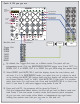
The lower drawing shows how the pulses look with pulse width set to 25%, in that
case the pulses looks like a “proper” clock divider where the longer the division the
longer the pulse. This creates overlapping and as a result the output looks more
interesting and is a mix of gate and trigger signals. This is very musical when using
envelope generators as it will dynamically alter the sustain portion of the envelope
like keys played on a keyboard. It is also very useful to insert mutes into pulse
trains of drum sounds, and as a gate sequencer to hold a long gate signals for
controlling elements like the DIRECTION on a Z8000 sequencer.
8
DIVIDER 1
DIVIDER 2
DIVIDER 3
DIVIDER 1
DIVIDER 2
OUTPUT IS THE SUM OF DIVIDER 1+2+3
PULSE WIDTH = 0%
PULSE WIDTH = 25%
OUTPUT IS THE SUM OF DIVIDER 1+2+3
DIVIDER 3