
User's Guide

ATOP3.5G Hardware User Guide
80447ST10636A rev.15 – 2019-11-21
Reproduction forbidden without written authorization from Titan Communications S.p.A. - All Rights
Reserved. Page 39 of 69
Mod. 0808 2011-07 Rev.2
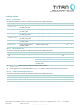
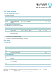
Table 21 Microcontroller clock
External crystal required for high-speed CAN, for all other purposes, internal RC oscillator is sufficient. Parameters mentioned
in this table are indicative and taken from supplier data sheets.
Symbol Parameter Conditions Min Typ Max Unit
f
xtal
crystal frequency in case of externally oscillator, connected to
MC_XTAL_1 and MC_XTAL_2
1 - 25 MHz
V
i(clk)RMS
RMS clock input voltage 0.2 - - V
t
cy(clk)
clock cycle time 40 - 1000 ns
t
clk(H)
clock HIGH time 0.4 ×
t
cy(clk)
- - ns
t
clk(L)
clock LOW time 0.4 ×
t
cy(clk)
- - ns
t
r(clk)
clock rise time - - 5 ns
t
f(clk)
clock fall time - - 5 ns
f
osc
oscillator frequency frequency of internal RC oscillator 3.96 4 4.04 MHz
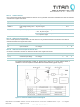
Table 22 Internal Real-Time Clock
An internal crystal generates RTC. Parameters mentioned in this table are indicative and taken from supplier data sheets.
Symbol Parameter Conditions Min Typ Max Unit
f
xtal
crystal frequency in case of externally generated clock - 32.768
- KHz
f
xtal
/f
xtal
relative crystal frequency
variation
20
- 20 10
-6
first year of aging
3
- 3 10
-6
TC temperature coefficient
0.028
0.034
0.04
10
-6
/C°²
T
turnp
turning point temperature
20 25 30 C°
t
d
delay time time to reach stability; at 25 °C, starting from
VDD_3V0 > 2 V
- 300 - ms
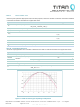
Figure 11 32 KHz deviation in ppm depending on temperature